|
Projects
|
Projects Welcome To KenSeibert.Com Audio
Let's take a look at the schematic as a whole, then discuss each of the parts. You can click on the schematic to see a larger version instead of squinting at the tiny one below.
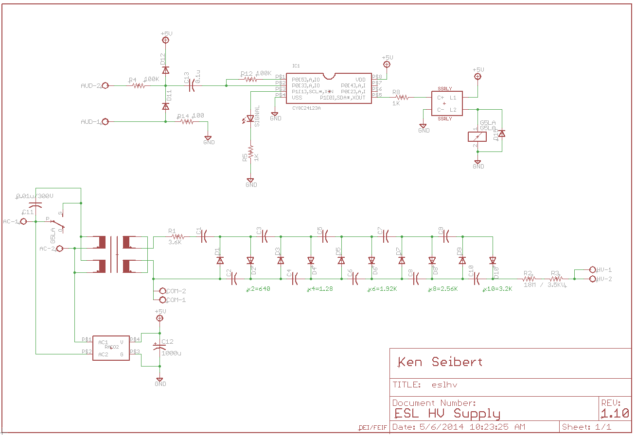
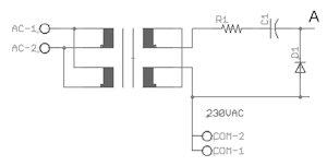
The lower section of the schematic is the voltage ladder. Rather than using a step-up transformer and capacitor filter as in a traditional unregulated supply, this HV supply uses a simple voltage doubler circuit. Referencing the circuit diagram below, if you consider a typical rectifier circuit, the voltage at point A would be roughly 1.414 * the input voltage. In this case we are using a small isolation transformer with the primary windings in parallel and the output windings in series. With 115VAC mains, this produces 230VAC on the secondary. 1.414 times this gives us roughly 325V at point A
We can expand on this circuit by adding an additional diode and capacitor. On the opposite half of the AC waveform, Capacitor C1 holds the 325V of point A while the voltage swings on the opposite side of the diode, D1, charging C2, through diode D2. When the voltage swings back, the bottom of D1 is at the high point, and with C2 charged, point B is now at about 650V, doubling the voltage.
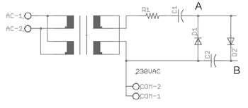
This same concept can be expanded in ladder fashion as far as needed to create higher and higher voltages. Our circuit for the HV supply uses 10 sets of the diodes and capacitors to give roughly 3.2kV.
Resistors R2 and R3 are used to current limit the diaphragm voltage. It is not current we want flowing to the diaphragm, it is charge on the diaphragm. Putting a couple of tens of Meg Ohms assures that there is no appreciable current flow. Resistors are typically not rated at this high of a voltage, so putting two high voltage resistors in series eases the load on each. Bear in mind, the actual voltage across the resistors is very small once the diaphragm charges.
The upper part of the schematic is an audio sense circuit. The input resistor limits the amount of current that this circuit uses from the audio signal and the diodes provide over and under voltage protection for the rest of the circuit. The capacitor isolates any DC component.
The heart of the circuit is a CY8C24123A microcontroller. It is a very powerful IC in that several functions can be selected and programmed into it - both analog and digital. And, it is a stand-alone device. No external components are required for operation (aside from a power supply).
This IC is set up with an Analog to Digital converter (ADC) monitoring pin 2. Pin 1 is an output of an internal analog ground, which is half way between Vcc and ground. This is used to bias the analog input to +/- about the ground reference. When the audio signal reaches a +/- threshold level, the program sets the system state as ON. In the ON state, the LED is lit, and the relay is set, applying power to the transformer.
We don't want the high voltage supply to turn off in the middle of a quiet passage in the music, so we use the controller to set a time delay. The system will remain on for 10 minutes after it no longer detects an audio signal. At that point, the state is set to OFF, the LED is turned off and the relay is turned off.
We use a small solid state relay to drive the large AC power relay, and an integrated 5V power supply to provide power to the microcontroller. When the system is OFF, very little power is used (a couple of mA) by the controller to monitor the audio signal.
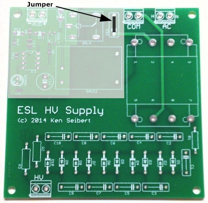
The board for this circuit is pictured below. It is about 4" square. If you are interested in using these boards to make your own ESL HV Supply, they can be purchased from the Store.
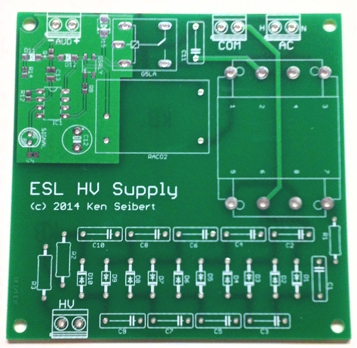
If you prefer to have the board be "always on" instead of sensing the audio signal, then you can omit all of the audio sensing circuitry illustrated in the picture below and install a jumper in place of C11