 |
Projects
|
Projects Welcome To KenSeibert.Com Audio
Once you have the board in hand, the next task is finding all the necessary parts. Below is a parts list for the softstart along with the Mouser part numbers and approximate pricing. Feel free to use your favorite resistors or capacitors... this list is just a suggestion and is meant to aid the person in collecting the parts.
Softstart Bill of Materials
| Ref Des | Part No | Description | Source | Qty Req | $ Each |
| C1 | 594-MAL203836101E3 | Electrolytic Cap, 25volts 100uF | Mouser | 1 | 0.12 |
| C5, C6, C7 | 72-VY2103M63Y5UG63V0 | AC Line Transient Shunt Cap | Mouser | 3 | 0.25 |
| D1, D2 | 1N4001E-E3/54 | General Purpose Rectifier | Mouser | 2 | 0.08 |
| J1-3 | 571-7969492 | Phoenix Terminal Blocks - 2 Pos, 5.08mm | Mouser | 3 | 0.75 |
| Q1, Q2 | 833-PN2222A-AP | General Purpose NPN Transistor | Mouser | 2 | 0.18 |
| R1-4 | 594-AC05W180R0J | 5W 180 Ohm 5% | Mouser | 4 | 0.59 |
| R5, R6 | RN55D1001FB14 | Metal Film, 1/8W, 1K, 1% | Mouser | 2 | 0.10 |
| RLY1, RLY2 | 653-G5LA-1-E-CFDC5 | G5LA General Purpose Relay | Mouser | 2 | 1.39 |
| U1 | 727-CY8C24123A-24PXI | Cypress PSoC Microcontroller | Mouser | 1 | 2.40 |
| U2 | 919-RAC02-05SC | 5V Integrated Power Supply | Mouser | 1 | 12.78 |
| 571-1-2199298-2 | 8-pin IC Socket | Mouser | 8 | 0.09 | |
| Printed Circuit Board | KenSeibert.Com | 1 | 8.00 |
In general the strategy to board assembly is to solder on the smallest parts first. In this case, I like to start with the ICs or IC sockets. They will be held in place when the board is turned over and placed face-down. Bending over the opposing corner pins slightly will keep the sockets from falling out when the board is turned. ICs usually have the pins at an angle. You need to slightly press the pins together to get them into the holes, but then the angle of the pins will hold the part in place when the board is turned.
Next is to install the low, 2-leaded parts - resistors, diodes, etc. I find it helpful to use a lead-bending gauge to get consistent length bends. I think it makes for a better looking end product. One is certainly not required, but they are inexpensive enough, around $5 at most electronics stores. Techni-Tool, Jameco, and others make them. I have had mine for about 30 years and have no idea where I got it.

Insert the resistors & diodes into the approprite slots, then hold them as you tip the board on end.
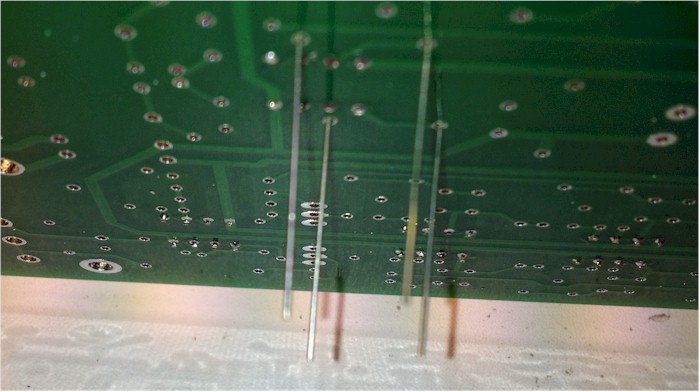
The parts will tend to fall out of the holes on the board unless you bend the leads slightly outward. This keeps the parts snug to the board for soldering.
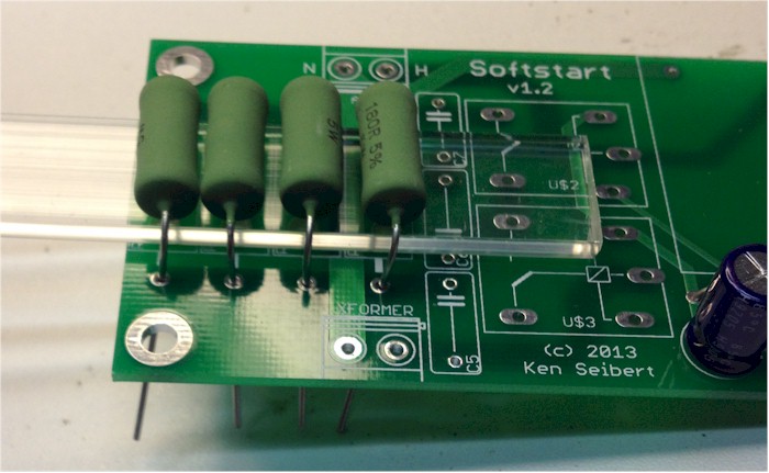
When installing the power resistors, you want to have them lifted slightly form the surface of the board. There are holes in the board to allow air to circulate and cool the resistors. By slightly elevating the parts this will allow for better airflow. I used a strip of acrylic but you could use anything - a strip of wood, bar of metal, etc.
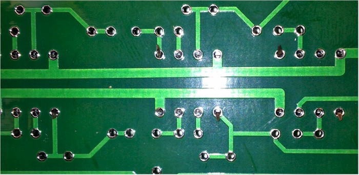
With the board lying face down, apply the soldering iron to the junction of the lead of the part and the solder pad on the board. Let it heat up for a second or two, then apply a small amount of solder. Keep the iron in place until the solder has flowed to cover the pad and whet to the lead. Remove the iron and let the solder cool without moving the lead or board.
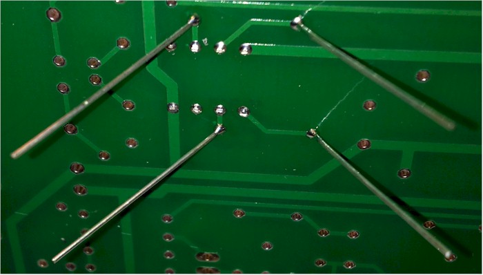
If the lead moves while the solder is cooling, you may get a weak joint that may fail in the future. If so, re-apply the iron until the joint is smooth and shines, then let it cool again. Adafruit has great illustrations of common soldering problems and how to repair them. The photo below comes from their site.

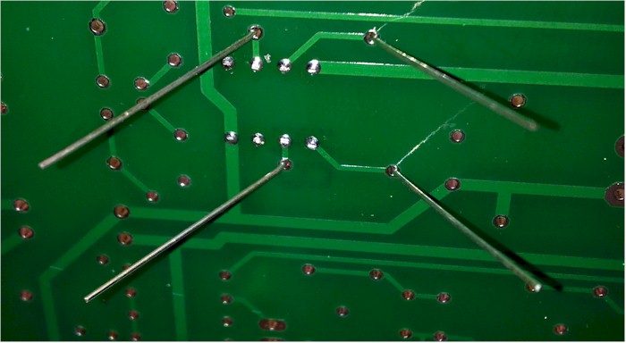
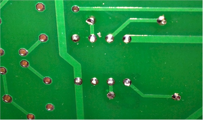
After the the parts have been soldered, trim the leads close to the board.
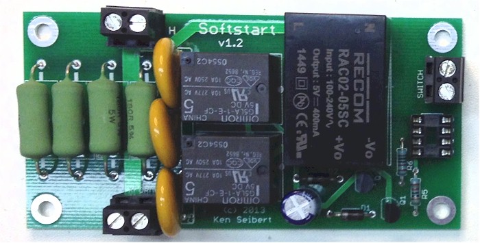
Repeat this process for progressively larger parts, like the transistors then larger resisitors, etc, finally ending up with the connectors, relays and power supply. When you are done, it should look like this:
Sometimes soldering leaves a residue of flux on the board. If you use a solder meant for electronics (non-acid, pure rosin flux) there is no need to clean the flux from the board. In faact it leaves a thin protective layer over the solder joints, but can be non-attractive visually. If you used a water-clean flux solder, then you must clean off the residue using water. The residue is hygroscopic and the scum-like layer can absorb moisture and conduct electricity. If you do use a flux cleaner, remember that they are not "spray-and-wipe", you need to use a brush (a tooth brush works well, just don't use it on your teeth afterwards).
The board, a kit of parts of an entire built and tested unit are available from the store.