 |
Projects
|
Projects Welcome To KenSeibert.Com Audio
The final step of the electrostatic speaker is assembling the various components into a finished unit.
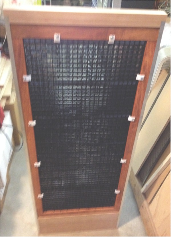
The stator panels have lead wires coming out of the bottom of the panel. These fit through the holes in the diaphragm frame, allowing the stator to lay against the pieces of tape on the diaphragm.
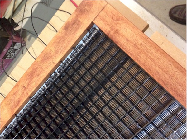
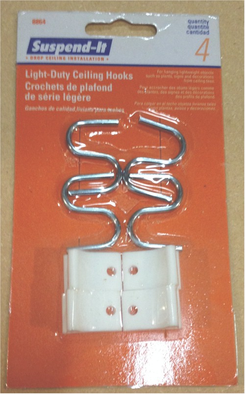
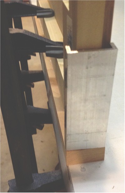
If you are assembling a permanent panel, you can remove the backing paper from the foam tape before inserting the stator panel. This will permanently affix the panel to the diaphragm assembly. In my case I want to be able to change pieces out at a later time, so I leave the backing paper on. To hold the stator panel in place, I use half of a clip from a drop ceiling retainer.
I split these into two pieces. They are just flexible enough to hold the panel into place without pushing too hard on the mylar diaphragm. I use several of them spaced around the periphery of the panel. Do not overtighten. If you do that it will squeeze the foam tape and reduce the diaphragm to stator spacing, or even cause the diaphragm to touch the stator. If this happens, the speaker will not work. The clips should be just tight enough to hold the stators in place. The process is repeated for the other side of the assembly. When you are done, it should look something like this:
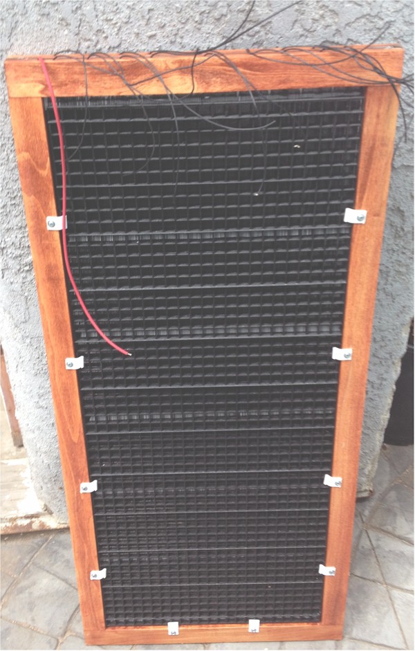
Once I was happy with the system I had, I removed the clips and took off the foam tape backer, then attached the stator panel to the diaphragm using the tape. This eliminated the need for the clips.
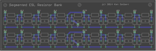
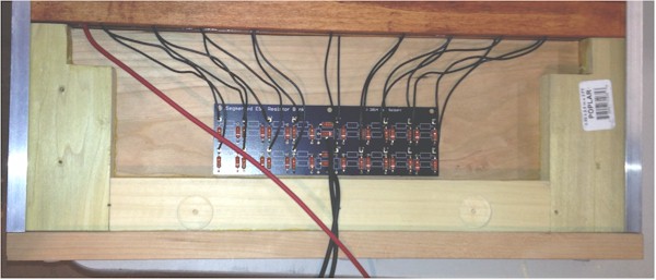
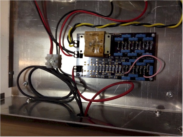
The segmented panel has a series of resistors between segments as well as an input resistor for each side. A spreadsheet available on DIYAudio.com written by Bolserst gives the formulation for the segmentation. The link to the spreadsheet is in post #67. Since I wanted to be able to experiment with different values, be able to tune the resistances, and use the resistors I had on-hand, I made a circuit board that allowed me to use a single resistor, put two resistors in parallel or put two resistors in series for each position.
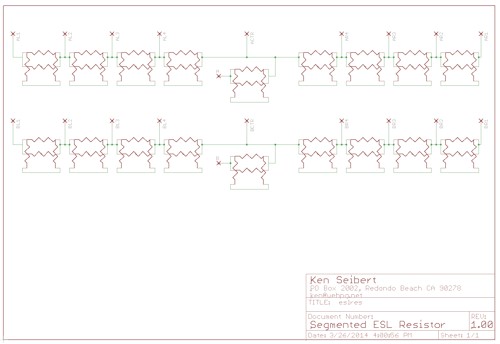
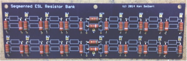
And then the completed board
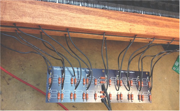
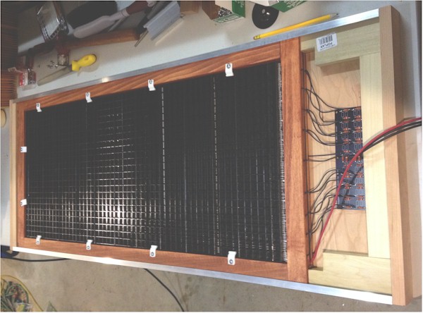
The lead wires from each segment are soldered onto the board then flexible lead wires are run from the board to go to the electronics box. For the long flexible leads I like to use probe wire. It can take many bends before breaking and has a high insulation value. It is fairly inexpensive at $0.25 per foot from Torrance Electronics
This is a good point to try out the panels by hooking up the electronics box. Use the terminal strips to attach the front stator wire to the red lead and the back stator panel to the black lead. Attach the diaphragm lead to the HV terminal block on the HV supply board. Plug everything in and try it out. This is a good point to fix anything that may be wrong in the setup. Don't forget to put a fuse in the power entry module!
If you are happy with the way everything is sounding, then proceed with the speaker building.
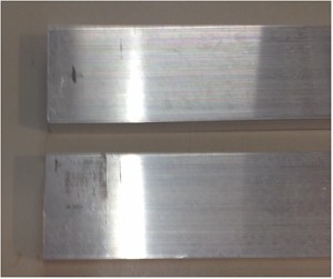
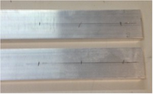
To hold the entire assembly together, and to give it decorative appeal and some strength, I have made a framework out of aluminum channel and wood. The aluminum chanel is 1.5" x 0.5" with a 0.125" wall. Unlike many aluminum channel extrusions, this one has squared-off right angles on the inside corners. With 1.5" width and two walls of 0.125", the inside width is 1.25" which just fits the completed diaphragm/stator assembly. I purchased the channel in 8ft lengths from Orange Aluminum for about $22 each. Shipping was very reasonable and fast.
Cut the aluminum channel to length. This would be the finished height of your diaphragm/stator panel plus 3/4" for the top plus 6" for the bottom. The mark out for the mounting holes. Allow for one hole at the top for attaching the top piece which should be 3/8" from the end. then from the bottom end mark out three holes 1", 3" and 5" from the bottom.
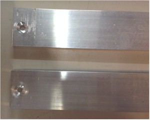
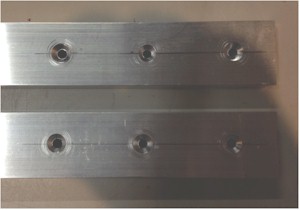
Next drill for a #10 screw clearance and countersink each hole.
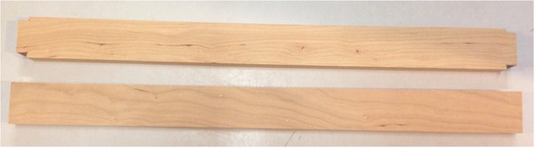
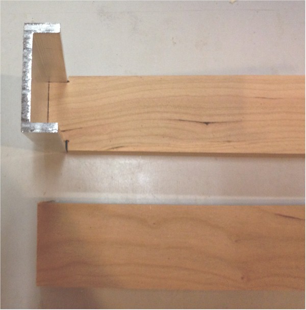
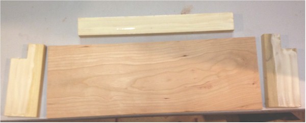
The wood pieces were made from Cherry because I like how it looks. You can pick any wood species, I am sure. The local woodworkers supply had pieces of cherry 1.5" wide and 3/4" thick. I used two pieces 18-1/4" long to make the top. One piece was notched for the aluminum channel, then the two pieces were glued together.
The completed top piece was then sanded. The top of the channel was drilled and countersunk to accept a #10 wood screw which then attached the top piece to the two channel pieces. Be sure to drill a pilot hole for the wood screw so that you don't split out the wood.
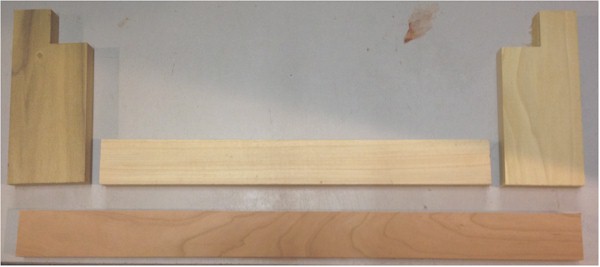
The bottom was made from a third piece of cherry 1.5"x 3/4" x 18.25", plus two pieces of cherry 6" x 3/8" x 17.25". I used an additional 2 pieces of poplar that I had laying around 3" x 3/4" x 6" plus a third piece of poplar 1.5" x 3/4" x 12
This provides a hollow space at the bottom for housing the resistor board as well as a point of attachment for the electronics box.
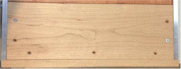
You can see above where the side pieces have a notch cut out of them. The ESL panel rests on these supports and the lead wires come out of the bottom of the panel close to the edges. The notch is so that the lead wires are not pinched between the support and the panel.
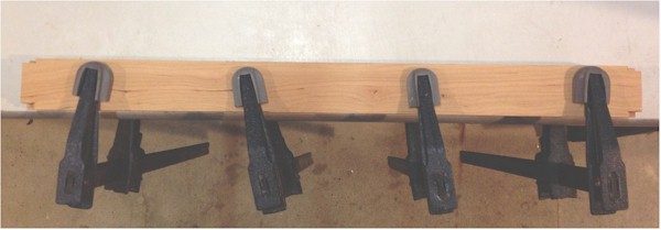
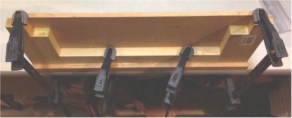
Glue is applied to the poplar pieces except near the long edge of the upright pieces. This portion hangs over the edge of the cherry panel. Use a piece of scrap channel to help align the uprights to the panel.
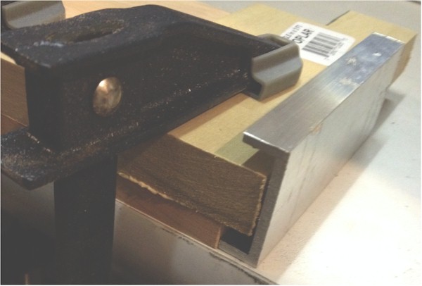
Then clamp and allow to set.
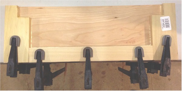
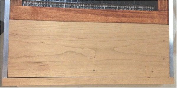
When the glue has dried, remove the clamps and sand the bottom of the glued assembly smooth, removing any glue bumps. Then use another 1.5" x 3/4" x 18.25" cherry strip for the bottom trim piece.
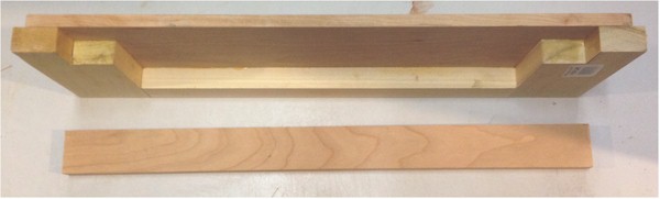
Align the edge of the cherry panel with the edge of the cherry strip. This will be the front of the speaker. Use a scrap piece of the channel to make the right spacing on the ends, then glue and clamp.
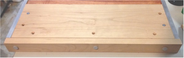
Once the glue has dried, assemble the panel, top piece and bottom pieces together. Be sure to drill pilot holes for the screws to keep from splitting out the wood.
Now, cut the remaining cherry panel to size to fit within the back opening. We will use short wood screws to attach this panel to the bottom of the speaker assembly. This will allow us to open the back panel to access the resistor board if necessary. Drill and countersink a few holes onto the panel to allow the holes to line up with the poplar pieces inside.
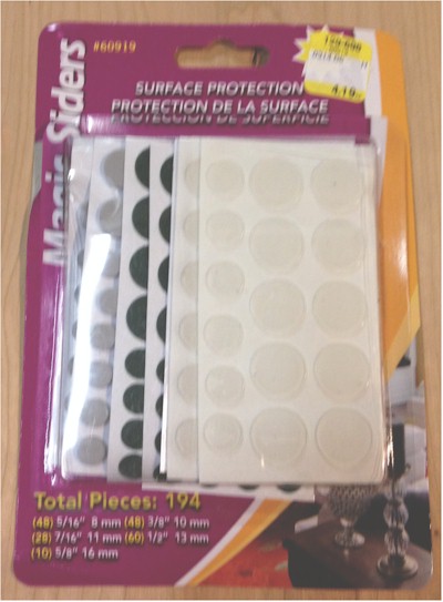
Drill pilot holes into the poplar for the wood screws then attach the back panel using a couple of the screws. This is only a temporary attachment. Affix two or three felt pads onto the bottom piece. I used some from a pack I got at a True Value store several years ago.
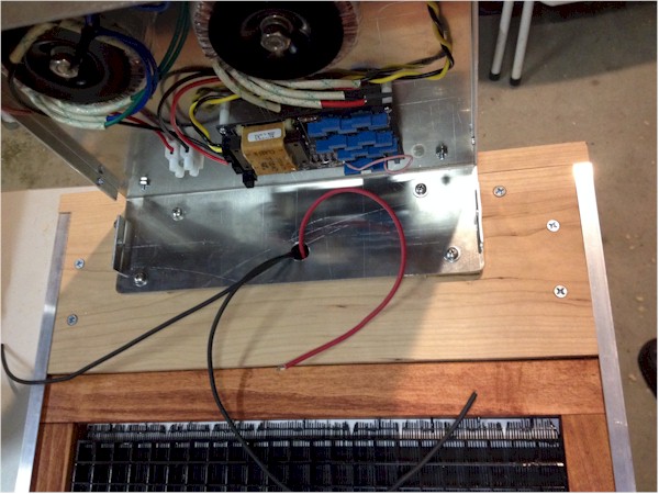
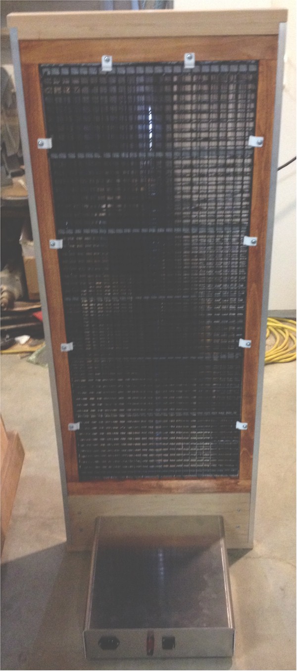
This is to keep the wood bottom from scratching up any cabinetry this speaker will sit upon. We are doing this now because the next step requires the final dimensions, including the felt pads. With the top cover off of the electronics box, stand the panel up and align the back of the box with the back of the panel. Be sure the panel is precisely vertical. Now, take a pencil and mark the locations of the mounting holes and wire access hole on the back panel.
Remove the electronics box and lay the panel back down. Drill the mounting holes to fit some #10-32 Tee Nuts. I got these at the local True value store, but they have them at Home Depot and Lowes for about $1 for a pack of 3 or 4.
Then drill out the wire access hole. I used a 1-1/2" forstner bit, but you could use a hole saw or a large drill bit, whatever works for you. Flip the panel over and press-fit the Tee Nuts into the panel. Some Tee Nuts have large tangs wich could split out the cherry wood, so use common sense in fitting these. I had to drill out pilot holes for the tangs.
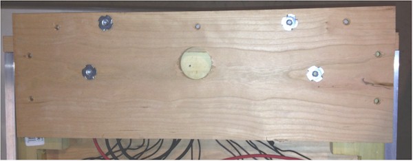
In my case, the bottom two mounting holes aligned with the bottom poplar strip. Since the Tee Nuts sit raised above the plane of the panel, I had to hog out some of the poplar so that the panel would sit flat.
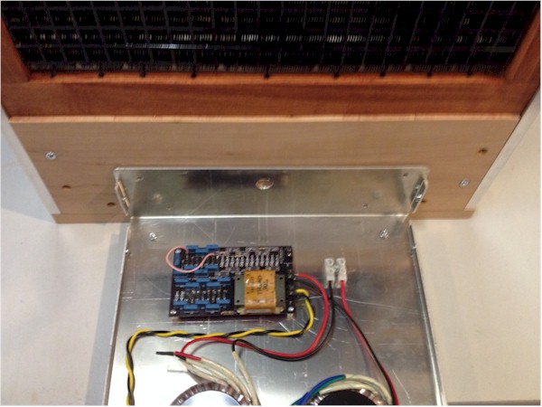
Pull the lead wires through the hole in the back panel and attach it using all of the wood screws.
If you look at the electronics box when the cover is on, the lid overhangs the front and back panels by about 1/4". To allow the panel to attach firmly and squuarely to the box, we need some spacers. I used the left over ends of the poplar strips that I used to make the diaphragm to fashion a couple of spacers. I'm sure you can use whetever you want for this.
![]()
Use 10-32 x 3/4" machine screws to attach the panel to the electronic box
Use the flexible leads to attach to the terminal strip for the stators and to the HV Supply for the diaphragm.
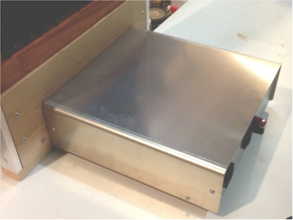
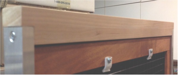
Affix the cover onto the electronics box, and we are done!
Of course, I disassembled the speaker after listening to it to finish the wood pieces with a stain and polyurethane coat and to surface and paint the aluminum. The end result is what you see on the home page.