 |
Projects
|
Projects Welcome To KenSeibert.Com Audio
Operational Amplifiers (more commonly called Op Amps) are a basic building block of modern electronic circuitry. They were first described in the work of Clarence Lovell at Bell Labs in 1940 while he was working on analog computing. In 1947 John Ragazzini coined the name “Operational Amplifier”, but it was in 1967 with Fairchild's release of the UA741 op amp that the use of these devices exploded. Today, op amps are found in nearly all electronic devices and there are hundreds or even thousands of types from which to choose.
It is first helpful to consider what an ideal op amp look like. Represented schematically, the op amp has a positive and a negative input, an output and two voltage rails.
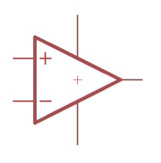
Some characteristics of an ideal op amp are:
- Infinite input impedance (draws no current from its source)
- Zero output impedance (able to drive any load)
- Infinite gain
- Zero current consumption
- Zero common mode gain (if the same voltage appears on both inputs the output voltage is not affected
- Zero offset voltage (if the inputs are equal, the output is zero)
Now, real op amps fall short in all of these areas, but to a certain extent, we can understand the functions of an op amp more easily if we consider an ideal case.
There are just a few circuit archetypes that are common to nearly all op amp circuits. We will look at some of there, but it will be helpful to remember the first rule of op amps:
The op amp will attempt to adjust its output so that its inputs are equal.
The first circuit archetype is the voltage follower in which the output is the same as the input. This circuit is commonly used as a buffer stage. A voltage exists in the circuit but the circuit cannot drive a low impedance load. A voltage follower is used to provide buffering drive capability to that voltage.
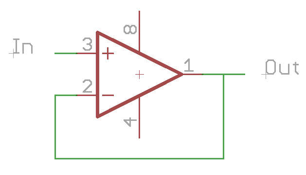
Since the op amp tries to make the two inputs the same voltage, the output will match the input.
This circuit is shown below. (Note that we have not shown the power supply rails.)
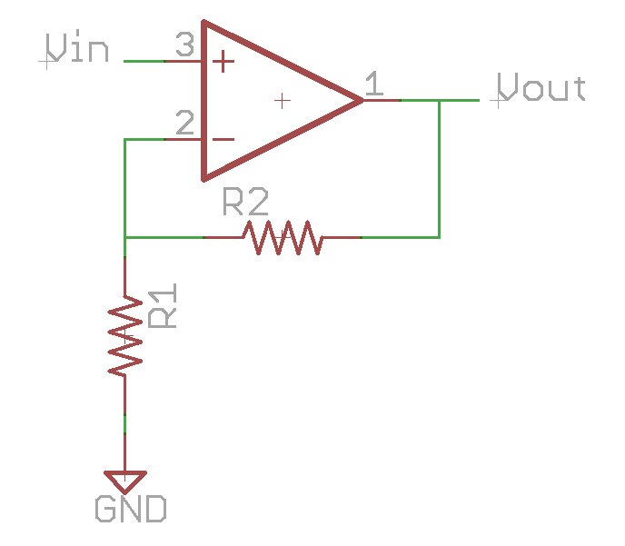
The voltage at the negative input can be calculated by the formula for a resistor divider circuit:
Vneg = Vout * (R1 / R1 + R2)
By the first rule of op amps, the positive and negative inputs are the same, this formula can be re-written as:
Vin = Vout * (R1 / R1 + R2)
The gain of a circuit (A) is the ratio of the output to the input, so in this case:
A = Vout / Vin
= (R1 + R2) / R1
= 1 + R2/R1
Note that with this type of circuit, the gain is always greater than 1.
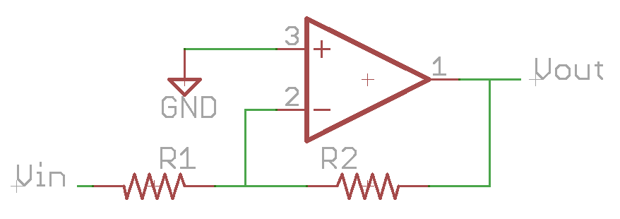
In this circuit, the input voltage and ground change places. Using our voltage divider function, the voltage on the negative input is now:
Vneg = 0V = (Vout – Vin) * (R1 / R1+R2)
And the gain:
A = Vout / Vin
= - R2/R1
Note than in this case, it is possible for the gain to be greater or less than -1.
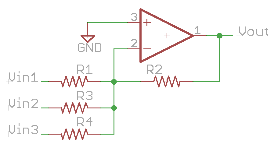
Remembering our first rule, the negative input will remain at 0V. If this is the case, then the effects of the voltage at Vin1 are independent of the voltages at Vin2 and Vin3. So,
Vout = - Vin1 * (R2/R1) - Vin2 * (R2/R3) - Vin3 * (R2/R4)
effectively adding each of the input voltages together with gain determined by the input resistor for each.
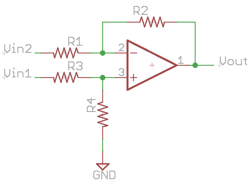
This is a combination of the inverting and non-inverting circuits.
Vneg = (Vout – Vin2) * (R1 / R1 + R2)
Vpos = Vin1 * (R4 / R3 + R4)
since by the first rule Vpos and Vneg are equal, then
(Vout – Vin2) * (R1 / R1 + R2) = Vin1 * (R4 / R3 + R4)
Vout * (R1 / R1 + R2) = Vin1 * (R4 / R3 + R4) – Vin2 * (R1 / R1 + R2)
Vout = Vin1 * (R4 / R3 + R4) / (R1 / R1 + R2) - Vin2
If, for example, we allow R1 = R2 = R3 = R4, then we find
Vout = Vin1 – Vin2
So far, we have been dealing with ideal op amps. In real life, however, op amps are not ideal. They all fall short in some or all of the characteristics that we laid out earlier.
- Infinite input impedance – Real op amps have a finite input impedance. Because of this, a current will flow into each if the input pins on the op amp. The resistors on the input pins will have extra current flowing through them, causing a voltage to develop across the resistor that will change the output. Some op amps are optimized for very high input impedance for situations where this is a prime consideration.
- Zero output impedance – Some op amps are much closer to the ideal than others and can drive lower loads. Most op amps can drive loads of several hundred ohms without fault, but are much more comfortable with loads in the kOhms. Some op amps are optimized to drive low impedance loads and can drive tens of Ohms easily. Some are even power op amps and can drive a loudspeaker directly.
- Infinite gain – The open-loop gain of op amps is very large, but not infinite, and it varies by frequency. 100dB of open loop gain is not uncommon, with some much higher. However, this gain drops off with frequency, and may be unity gain as low as 1MHz. Specialized op amps can have significant gain into the tens of MHz.
- Zero current consumption – Op amps that have a high bandwidth or higher gain typically consume more power than those than are lower performance. Also, those that are able to drive lower impedance loads typically consume more power than those that are not optimized to do so.
- Zero common mode gain – If both inputs are driven with the same voltage, say a sine wave, this sine wave will show up on the output (much reduced). Op amps are specified with a Common Mode Rejection Ratio (CMRR) of several tens of dB, sometimes more than 100dB if the op amp was optimized for this.
- Zero offset voltage – If both inputs of an op amp are grounded, the output of the op amp is close to, but not zero volts. How close is again a matter of optimization.
The art of circuit design with op amps is in balancing the real characteristics of the parts to meet or exceed the circuit requirements. Op amps can be purchased that are very close to ideal in all these areas, but they may cost over $100 per op amp. If the requirements of the circuit are such that they can be met with a non-ideal amp with careful design, then why spend $100 when a $0.25 op amp will do.
Given this, there are some general guidelines that will help the designer compensate for non-idealities.
Keep input impedances similar
Since there is some input current on each pin, it stands to reason that if we can keep the input impedances the same, then we can minimize the effects of this current.
Let's look at the case of the inverting amplifier.
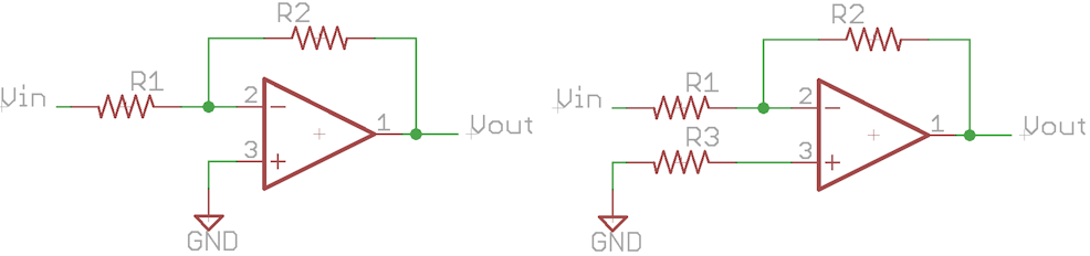
The two versions are theoretically the same. If the op amp were ideal, there would be no difference between the two. Vpos is still at ground in both cases and the gain is the same. The fact that the input impedance is non infinite means that there is an offset relative to the currents through R1 and R2 in parallel. In the diagram on the left, since there is no corresponding resistor on the positive input, there is an imbalance between the offset on the positive and negative inputs. This will cause an error on the output. If, however, as in the diagram on the right, we put in R3 which has a value of R1||R2, then the currents in each input produce the same voltage offset, nullifying the error.
Hit the sweet spot of component selection.
When you first were learning electronics, you probably talked of circuits with a 1 Ohm resistor, a 1 Farad capacitor and a 1 Henry inductor. Real-life circuits generally don't use these values, but rather use values appropriate for components available at a reasonable cost. In the same way, select components that the op amp is most comfortable using. If the resistor values are too low, the op amp will struggle to drive the currents necessary, and head outside of the linear region of operation. If the resistor values are too high, then the input currents will generate too large of offset voltages, and noise voltages will be higher. For op amp circuits, 10k – 20k Ohms is a sweet spot. Avoid going below 1k and above 100k Ohms for best performance. In some cases it will be necessary to do so, but then the selection of an op amp to minimize the issues will be necessary.
Watch component tolerances
. Often when designing circuits, especially differential amplifiers with gain, precision is the key. If you are using 1% resistors, remember that one resistor could be high by 1% and another low by 1%. If these are the input resistors to a differential amp that has a gain of 10, the output could be considerably off. In critical circuits, be sure to match resistors. They can both be off by 1% and the circuit will still be ok if they are both off in the same direction. Also remember to check for specialized components. There are differential op amps available in a single package that have internal resistors. These resistors are laser trimmed to very exacting tolerances – much more tightly matched than is possible with discrete resistors.