 |
Projects
|
Projects Welcome To KenSeibert.Com Audio
A filter is an electrical circuit that allows certain frequencies to pass through and other frequencies to be attenuated. They are broadly categorized as:
- Low-pass - a filter that allows low frequencies through but cuts off high frequencies.
- High-pass - a filter that allows high frequencies through but cuts off low frequencies.
- Band-pass - a filter that allows a range of frequencies through, but cuts off those that are lower and higher then the range.
- Notch - a filter that allows all frequencies through except those of a certain frequency range.
- All-pass - a filter that allows all frequencies through.
Let's look at the Low-pass filter first. Below is an idealized frequency response plot for a low-pass filter:
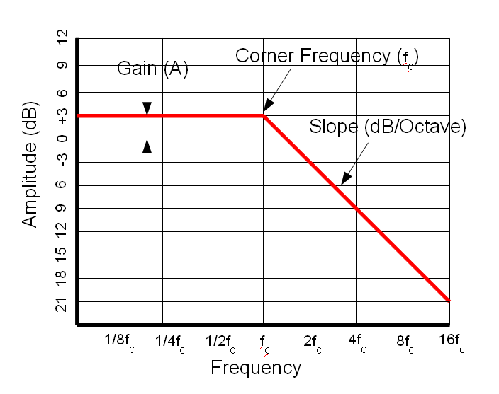
There are several points to note on this plot. First, note that it is a log-log plot. The Y axis is in Decibels. The Decibel scale is a logarithmic scale. In power terms, 10dB is a factor of 10, 20dB is a factor of 100 and so on. In voltage terms, 20dB is a factor of 10 (remember, power is proportional to voltage squared). Also note that the frequency scale is logarithmic. The center frequency is marked, then multiples of this frequency. In general, frequency respopnse plots such as this are log-log.
Some other points of note are indicated on this plot. The flat portion of the plot is at +3dB. This means that the output amplitude for these frequencies is 3dB higher than the input amplitude. This is called the Gain of the filter and is usually indicated by the letter "A". The frequency where the response begins to decline is called the Center Frequency or Corner Frequency and is usually written as Fc. The speed at which the response plot declines is called the slope. It is usually expressed in Db per Octave or dB per decade. An octave is a doubling in frequency, a decade is an increase in frequency by a factor of 10.
A high-pass filter has a similar plot:
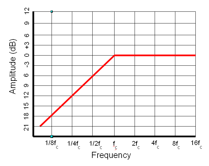
The same descriptors also apply to the high pass - gain, corner frequency and slope.
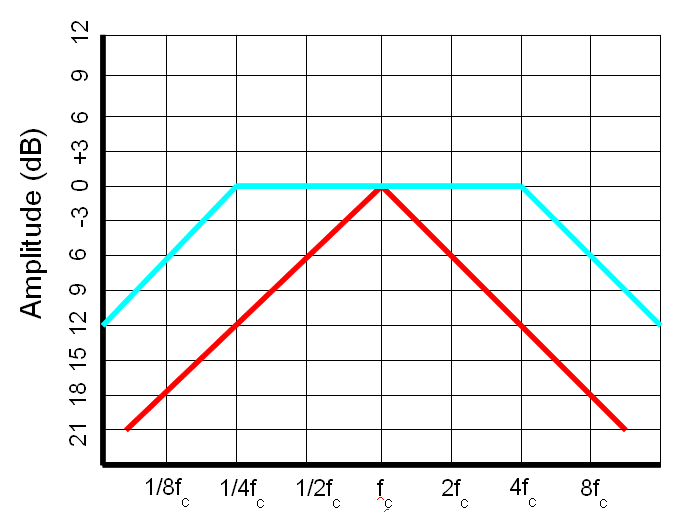
A Band-pass filter can be a cascade of a high-pass and a low-pass. In this case there are the high and low corner frequencies. It can also be the case where the band is very narrow, and in this case the high and low corner frequencies are the same. In this case it is called the center frequency.
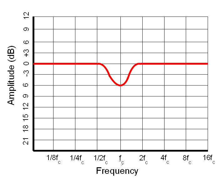
A Notch filter is also typically narrow. On this filter we can also see another specification of filters and that is the Q. Q is a measurement of the sharpness of a filter. It stands for "Quality" and is the ratio of the energy stored vs energy dissipated at the resonance of the circuit. A high Q circuit is very sharp. A low Q circuit cas a smoother transition at the center frequency.
You may wonder why one would even have an All-pass filter. What we are not showing are the phase plots. In each of these filters, there is a differing amount of phase shift on the transfer function. Sometimes it is useful to have the phase shift without affecting the amplitude. This is the function of the all-pass filter.
When a filter is discussed, it may be referred to as, for example, "a 1KHz low-pass at 12dB per octave". Or sometimes it is referred to as a 2-pole filter or a 4 pole filter instead of a filter with slope. This is a shorthand. Each pole in the filter results in a 6db/Octave slope. A 2-pole filter has a 12dB/Octave slope, a 4-pole filter has a 24dB/Octave slope, etc. (See What is a Pole? for more information on why they are called poles.)
Filters can be cascaded. This is where the fun lies. By placing the output of one filter into the input of the next, a steeper slope can be obtained, smoother response, and may other changes. Cascaded filters is how filter types such as Butterworth, Chebyshev, Bessel, Eliptical, Gaussian and others are obtained.