 |
Projects
|
Projects Welcome To KenSeibert.Com Audio
Nearly every electronic project needs a power supply. Some are a simple as using a wall pluggable supply (wall wart) some require considerably more. We will look at the most basic of power supplies, the unregulated linear supply.
In it's simplest form, a DC power supply consists of a transformer, a rectifier and a filter, as shown in Figure 1 below.
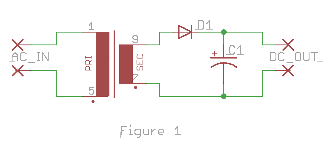
The AC voltage is applied to the primary of the transformer and then is stepped up or down based on the ratio of the number of turns of windings between the primary and secondary. For ecample, the transformer may have 100 loops around the core for the primay winding and 30 loops around the core for the secondary. This will step the voltage down using a ratio of 100:30 or 30%. If 100V AC is applied to the primary winding, 30V AC would be on the secondary.
As the AC signal goes positive, the diode will conduct, charging the capacitor. As the AC signal goes negative, the diode will block the current flow to the capacitor, allowing it to keep the charge. This will charge the capacitor to the peak value of the AC signal minus the voltage drop across the diode. This is called a Half-Wave Rectifier as the circuit only charges the capacitor during the positive half of the AC signal.
When a load is put upon the DC output, this will discharge the capacitor. When the next positive wave of the AC input comes again, it will charge the capacitor again. This cycle of charge and discharge is seen as a ripple voltage on the capacitor.
We can convert this circuit to a Full-Wave Rectifier by adding diodes as in the Figure 2 below.
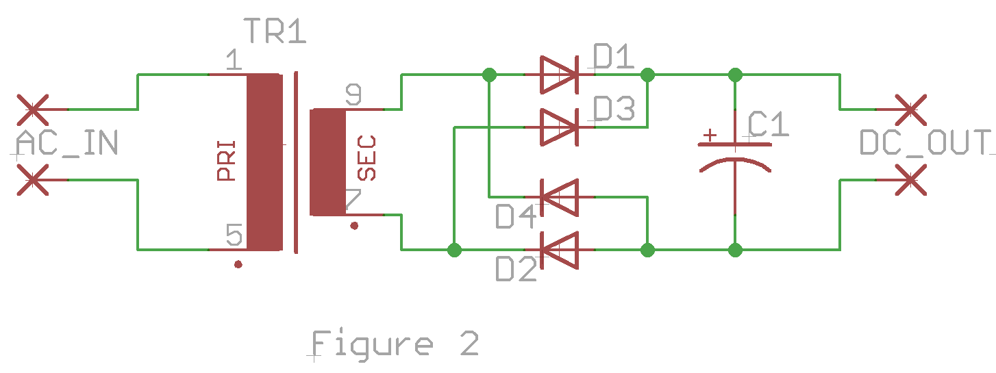
Here we can see that while the AC signal is positive, the current path through D1 and D2 charges the capacitor, and while the AC signal is negative, the current path through D3 and D4 charges the capacitor. This circuit makes use of both halves of the AC signal to charge the capacitor increasing the efficiency of the power supply. In addition, as the load is put upon the oputput, the capacitor only has half as much time to discharge before being charged again as it is charged on both halves of the signal. This has the effect of drastically reducing the ripple voltage of the DC output.
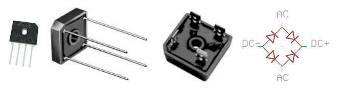
This is such a useful rectifier configuration that many manufacturers make a single package with the four diodes included as a Bridge Rectifier that take the AC signals in on 2 pins and have the DC signal out on 2 other pins.
The designer of a power supply has to have several factors in mind before starting, among other things:
- What DC voltage output is required?
- What is the tolerance on this output voltage (ripple allowed)?
- How much current does the power supply have to provide?
- What is the AC voltage supplied on the input?
- What safety requirements are there?
Lets take as an example that you wanted to have a bench top power supply for your circuit experiments that supplied about 12V DC at about 2 amps. You want to be able to run it from the 120V AC outlet and you are not particularly concerned about the ripple voltage, but want it to be fairly low.
To begin, let's consider the transformer. The transformer is specified by the primary voltage, the secondary voltage and the secondary current. The Primary and secondary voltages are typically RMS voltages, not peak voltages. The peak voltage for a sinusoidal AC signal is the RMS voltage times the square root of 2, or RMS * 1.414. In addition, we have to take into account the voltage drop across the diodes, which is 0.5V to 0.7V per diode. There are 2 diodes used on each half wave, so we have to allow for an additional 1.0 to 1.4 volts. The diode bridge specifications will give us this number, but let's assume 1.1V
DC Output voltage = (Secondary voltage * 1.414) – 1.1V
Shuffling everything around using basic algebra, we get;
Secondary Voltage = (DC Output Voltage + 1.1V) / 1.414
= (12 + 1.1) / 1.414
= 9.26V
So, we will want a transformer that is 120V primary, 9VAC secondary.
The voltage on the output drops during load between charging cycles, but the capacitor does not drop to zero volts. This means that if the voltage only drops a volt or so, the diodes will only conduct when the voltage on the AC waveform is greater than the voltage across the capacitor. This only happens during a small portion of the waveform

If the circuit is charging the capacitor only during 25% of the waveform, but the load is using current during 100% of the waveform, then all of that current has to happen during the 25% of the time. To a first order approximation, if you charge ¼ of the time, you need 4 times the current during the charge. Transformers are not closely specified in terms of current. In other words, the current spec is not a peak, instantaneous current permitted, but closer to an average current. You could probably get by with a 2 A transformer for your 2A supply, but good engineering practice will allow for some margin, especially if the peak current is so high.
The specifications for the diode bridge are much more tightly specified. They can handle much larger non-repetitive surge currents without burning up, but the charging of a capacitor is repetitive, so be sure to allow for the peak current in the specification. In this case, we want to be sure out diode bridge can handle in excess of the the 8A charging current we will encounter. Also bear in mind that for some of these bridge rectifiers, heat sinking is required to handle the rated current.
For a 60hz AC input, the ripple voltage in the DC output can be approximated by
Vripple = Vdc * 0.0024 / RC
where C = the capacitance of the filter capacitor, and R = the load resistance. For a supply of 12V and 2A, the load resistance can be calculated using Ohms law:
R = V/I
= 12/2
= 6 Ohms
For example, allowing for a 0.5V ripple voltage in our supply, we can plug these values into the equation above
Vripple = Vdc * 0.0024 / RC
C = Vdc * 0.0024 / R * Vripple
= 12 * 0.0024 / 6 * 0.5
= 0.086 (or 86,000 uF)
That is a faily large capacitor. The value of the capacitor as you can see is inversely proportional to ripple. Double the ripple, halve the capacitance. Capacitors are specified primarily by their working voltage and capacitance. Be sure the capacitance is at least as large as the ripple equation specified and that the working voltage is greater than the largest voltage the circuit will ever see.
One of the advantages of a large capacitor is that it can store enormous amounts of energy. When you are working on a circuit, one of the disadvantages of a capacitor is that it can store an enormous amount of energy – then discharge into you! You must take care than the capacitor is discharged before working on the circuit. To do this, it is a good idea to place a resistor across the capacitor to bleed off the charge when the circuit is turned off. The load resistor is a fairly small value, 6 Ohms in this case. It is typical to make the bleeder resistor two orders of magnitude larger than the load, which would be 600 Ohms in our example. This will permit a reasonably short discharge time (a minute or so to a safe level).
This resistor will see a voltage for the entire time the power supply is on, so we must be sure that it is capable of handling the power dissipation.
P = VI
= V*V/R
= 12 * 12 / 600
= 0.24
So, in this case, we will want to use at least a ¼ W resistor, but to be safe, use a ½ W resistor.
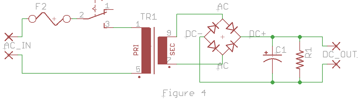
We never want to plug something into the wall outlet without proper fuse protection, and most likely will want a switch as well. When we add these items to the circuit, we finally get the circuit below in Figure 4
Very common in audio circuits is the need for a split or balanced power supply, for instance +12V and -12V. This type of supply is very similar to the unregulated supply above, except we need to divide the voltage output in half. One simple way to do this is by using a dual-secondary transformer or a center-tapped transformer.
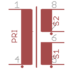
The symbol above is a transfermer with two secondary windings. Note on the symbol there is a dot next to some of the wires. This indicates the polarity. If current is flowing toward the dot in the primary, it will also flow toward the dot in each of the secondaty windings. A center tapped secondary is just like the above, except that the center two wires of the secondaries are connected together.
Figure 6 below shows how we would adapt the unreguated power supply from above to be a split supply.
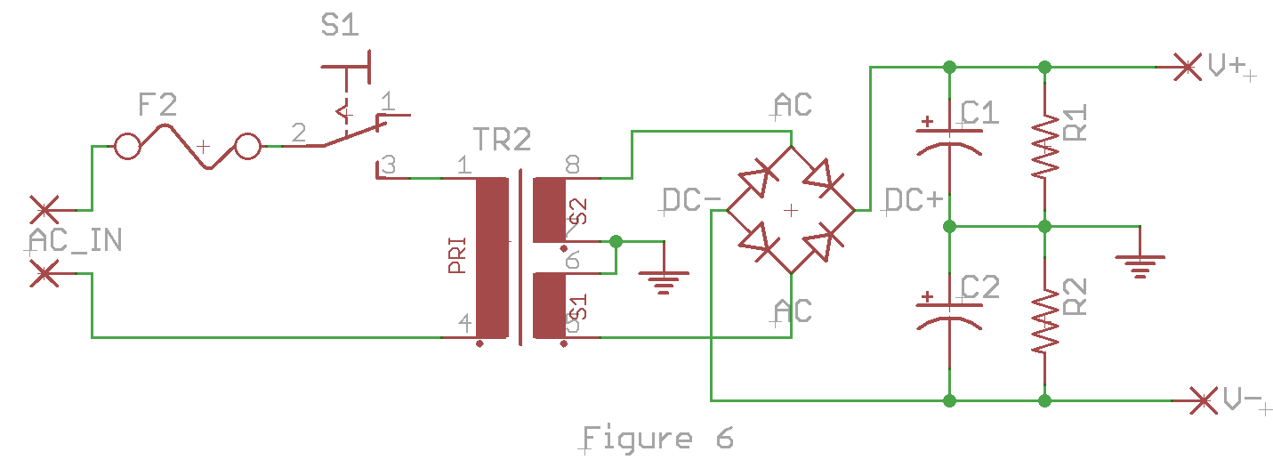
By tying the secondaries together or using the center tap, we can create a common ground reference between the two output voltages. Then by doubling the filter capacitors and bleeder resistors, we create a pair of supplies, plus and minus, around a common center.
All of the calculations we have done before hold just as well for this example. If instead of a single 12V supply we want +/- 12V, then we use a transformer with two 9V secondaries or an 18V center tapped secondary. Each capacitor is the same, each resistor is the same. The current in the diode bridge is the same, but the voltage is now doubled.