 |
Projects
|
Projects Welcome To KenSeibert.Com Audio
The electrostatic force is small in comparison to an electromagnetic force (what drives most loudspeakers) so the object being moved must be very light. Most ESLs use a thin mylar sheet, about 6 microns thick. Think of a stiffer and thinner version of the plastic cling wrap you use in the kitchen, and you will be close. Since the diaphram is driven evenly over the entire surface, it does not have to be really stiff as a typical spealer cone. This also allows the diaphram to be very light. In a large panel, the diaphram has about the same mass as a cubic inch of air. Since the forces are small, a large panel is required to achieve reasonable sound pressure levels. A 6" x 12" ESL panel will be plenty loud enough to hear well, but it will not offer room-filling sound. This is why most ESLs are typically large panels.
The material I used for the diaphragm is a 6 micron mylar purchased from a vendor on ebay. It is $30, free shipping and 40m long, enough to do many panels with extra for goofs or experimentation.
Electrostatic Speaker Membrane Dupont Mylar C 6um 40M
On the forums, you will see many examples of ESL panels where the diaphragm is attached directly to the stators using double-sided foam tape. In my case, I wanted to be able to change out stators as I experimented with different configurations. If the diaphragm is taped to the stators, it is difficult to separate the panels to redo the stators. It will destroy the diaphragm and each time a new diaphragm has to be made. To avoid the, I created a frame to hold the diaphragm then attached the stator panels to this frame. This allowed me to have a permanent diaphragm and then experiment on the stators at will.
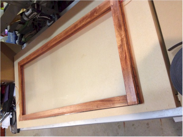
The diaphragm frame is made of wood. If I were a good woodworker or posessed the right tools, I'd probably just dado the ends of the frame pieces or use dowels to make a good, solid frame. Since neither are the case, I constructed the frame from 1/4" x 1-1/2" slats of poplar from Home Depot. They have Maple, Oak and other more fancy woods, but for my skill level, poplar was fine. The inside dimensions of the frame are 1/4" larger then the dimensions of the stator panels. In this case my stators were 15" x 36", so the inside dimensions of the frame are 15-1/4" x 36-1/4".
The frame was made by overlapping the ends of the slats and securing everything with glue. The photo below shows the overlapping scheme. The only power tool I used was a power jigsaw to cut the ends of the slats to length.
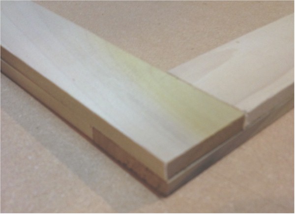
These were glued and clamped with spring clamps from Harbor Freight. The side and end pieces were glued and clamped first, then assembled into a completed frame later. I drilled holes through the bottom piece of the frame to allow the segment feed wires to pass through before assembling the final frame. The stator panel itself served as a square reference for gluing the final frame properly. When all is said and done, this makes a fairly sturdy frame for the diaphragm. Once the frame was made, I sanded and stained the frame.
Four frames are necessary for a stereo pair of ESL panels, 2 front frames, and 2 back frames.
The mylar has to be under tension. If you do not tension it, then the diaphragm will flop around until it sticks to one stator or the other. After that, no sound. When you tension the diaphragm, it acts as a drum head, vibrating with a resonant frequency. The higher the tension, the higher the frequency. When the ESL is completed, this resonany frequency determines the low end of the frequency range the panel will produce. If you have a resonance of 100Hz, then the panel should be crossed over no lower than 200Hz if you have a good 4th order filter, higher than that for a 2nd order filter. The balancing act is to tension the diaphragm enough so that it behaves reliably but not so tight as the resonance is too high. The rule of thumb is that it the mylar should be stretched 1% to 1.5% to achieve the proper tension.
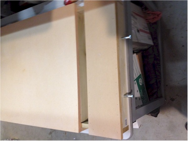
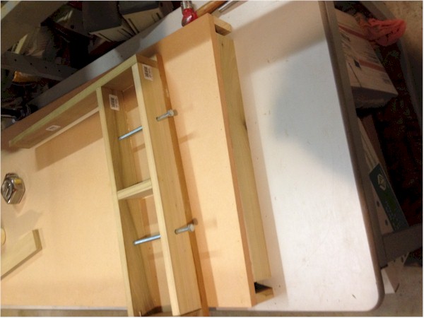
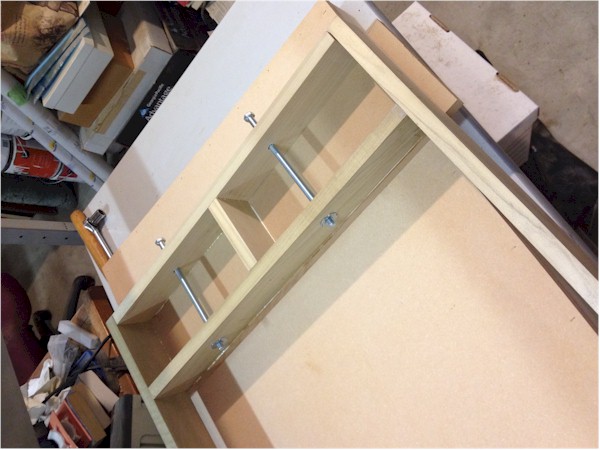
One common method is to use an inner tube stretching table. You can find instructions on making one of these on diyaudio.com. I made a smaller table for my first few ESL panels, and it worked OK, except that it put the same force on both axes, stretching the narrow axis a greater percentage. In this case, I wanted the majority of the stretch along the major axis, similar to how Martin Logan constructs their panels.
The photos below show how I constructed a stretching table. The idea was to have a small moveable piece at the end which could be drawn our by turning some bolts. 1/4" marks on one of the legs tells me how far the mylar has been stretched. I taped the mylar at the top and bottom very well, then turned the bolts to the proper stretching level, then manually pulled and taped the sides to remove any wrinkles in the mylar. In this case, I had a piece of mylar that was 44" long. Stretching 1.5% of this length worked out to about 5/8".
One side of a frame is covered with double-sided foam tape from Uline. It is $12 for a 36yd roll, and one roll was sufficient for all four frames.
S-10530BL 1/16" thick x 3/4" Foam tape
Two pieces of tape are laid side by side to cover the width of the frame. Other ESL assembly guides show only one width of tape. I prefer the security of a double row and the extra insulation it gives from the charge ring (later). Once the backing paper is removed, the frame is laid tape down onto the stretched mylar and firmly pressed to attached the mylar securely. Finally trim the mylar to the outside of the frame with a razor blade or craft knife.
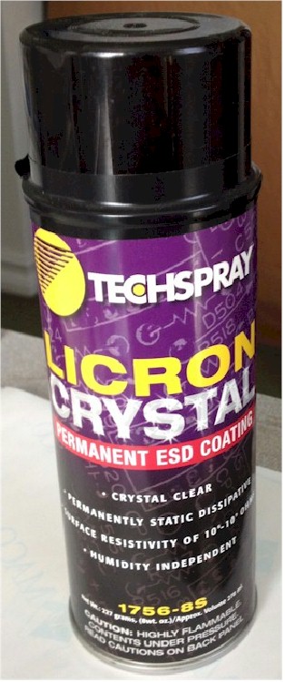
The next step is to coat the Mylar. Mylar, in and of itself, is non-conductive, so in order to retain the charge on the diaphragm, the entire diaphragm should have an electrical resistance of 10^9 to 10^12 Ohms. Entire schools of thought and process have come about regarding coatings. A perusal of the Exotics section of http://www.diyaudio.com will give you a dozen coating formulas or processes. Everything from dish soap to craft glue to graphite and cotton balls. I have had excellent results using an anti-static spray product called Licron Crystal. It sprays on easily, dries quickly, and is impervious to humidity. One thin complete coat is all you need. It gives a surface resistance on the low end of the desired range, but works really well. I purchased it through Mouser. The other coatings have their main attractiveness in that they are very inexpensive. Licron is not. It is about $40 per can, which contains enough to do several panels. I am still on my first can of Licron and have made well over a dozen panels of various sizes before settling on this design.
You don't need or want to coat the diaphragm all the way to the edge of the Mylar, only about halfway through the edge tape, so you can use painters tape to mask off the places you don't need to coat. Lay the panel with the diaphragm flat, with the diaphragm up. Spray a thin coat of Licron over the surface of the diaphragm, using enough spray to just wet the entire surface. The spray is mostly solvent, which will evaporate leaving a very thin, clear coating of slightly conductive material.
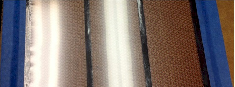
Do your best to do the coating in as clean and dust-free environment as possible. Everything will stick to the Licron when it is wet. Be sure to dust off the Mylar before coating. This panel was just sprayed with Licron and you can see a slight haze to the Mylar where the coating is still just wet.
The instructions on the can say to allow 24 hours for complete curing – believe it. The foam tape will not adhere easily to uncured Licron. I have found it best to allow even more time for curing before proceeding, especially if I am doing a panel in the winter (well, OK, Southern California winter) where the temperature is below room temperature and humidity is high. In the hot, dry summers here, the curing is far faster.
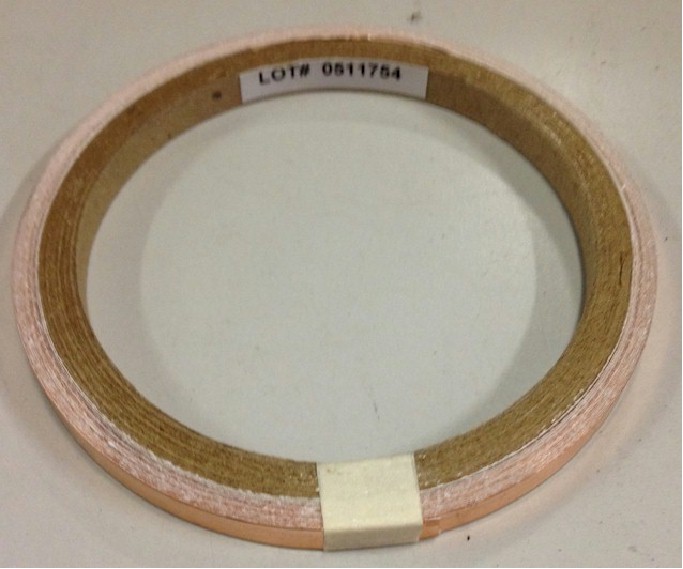
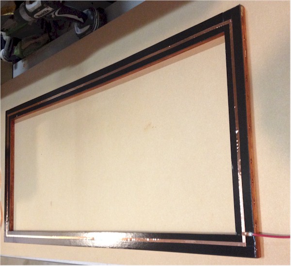
Once the diaphragm is tensioned and coated, a method has to be in place to allow charge to be placed on the diaphragm. In this instance, it is a ring of copper around the edge of the diaphragm, hidden between the layers of tape. I chose an adhesive-backed copper strip as the material for the ring. It is available from a number of sources, but as I was ordering the foam tape from Uline , that seemed as good a place as any to purchase the copper tape.
Copper Tape at Uline It is about $23 for 18 yards. Alternatively, McMaster-Carr has it for about $7 for a 6 yard roll (part number 76555A721) Copper Tape at McMaster. For a 15" x 36" stator, you will need about 9 feet, or 18ft for a stereo pair. Depending on just how careful you are, you may make it with one of the 6 yd rolls.
Using another of the frames affixed with the double sided tape, I remove the backing, then lay down a strip of the copper tape in the center of the strips, completly around the outside of the frame.
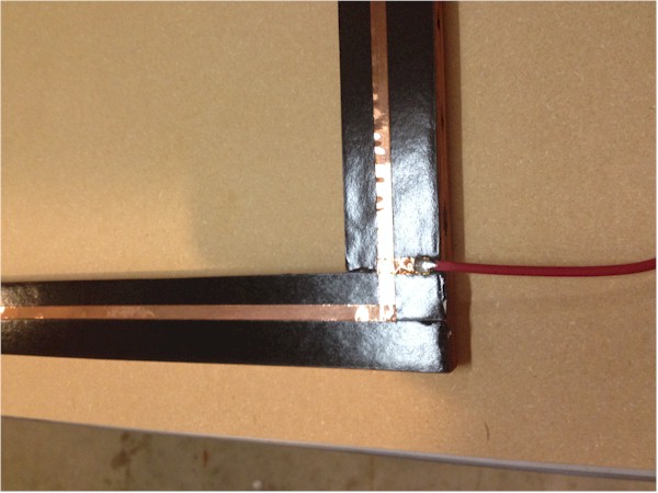
A connection must be made to the charge ring to the high voltage supply, so this must be soldered onto the copper tape before sticking it onto the panel. The copper solders easily, but the real trick is to make sure the solder joint is as thin as possible. Use fine stranded wire for this and fan out the strands of the wire so that they all lay flat on the copper. Let the solder flow onto the copper keeping it very thin – do not allow it to ball up. Use some fine sandpaper after the joint cools to knock off any rough spots, remember, sharp edges and points are too attractive to corona arcing and can ruin a completed panel. This is one reason I likle a double wide tape strip. By sealing the charge ring well inside the tape strip, that chance of arcing is greatly reduced.
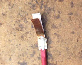
I like to trim down the insulation and the tape slightly where the wire sticks out of the panel so that the panel will still lay flat. I use probe wire for the leads to the charger ring. It is fairly inexpensive at $0.25 per foot (I get it at Torrance Electronics) and very flexible.
Now you have the two halves of the diaphragm assembly. Align one to the other so that the tape holds them together and press to make a good seal.
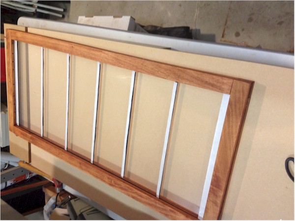
The last step in the diaphragm assembly is to place the spacer tape. The same foam tape used to hold the frame together is used as a spacer between the diaphragm and the stators. I place a full width piece at the top and bottom of the mylar, against the frame. Then I split the tape width in half using a razor blade and place several strips across the diaphragm. The spacing of these should be about 100 times the diaphragm/stator spacing. The tape thickness is the spacing, which is 1/16" or 0.0625". 100 times this is 6.25" so I placed these so that I have 6 evenly spaced areas, just under 6" each. This is done on both sides of the mylar.
If you have no desire to disassemble your panels later, you can remove the tape backing and affix the stators to the tape. In my case, I like to experiment, so I left the backing on the tape which allows me to remove the stators without damaging the diaphragm.
This completes the diaphragm assembly.