 |
Projects
|
Projects Welcome To KenSeibert.Com Audio
Since the forces involved in moving the diaphragm of an ESL are proportional to the voltage levels, and inversely proportional to the spacing between the stators and the diaphram, ESLs use high voltages. The voltages required are in the range of 2500V to 3500V, but the current required is almost zero. Unlike traditional speakers where the current through the voicecoil causes the force - no current, no sound - here it is the charge that matters. Once the diaphram has a charge, it will continue to work even with no power supply (for a time, until the charge dissipates).
If you increase the voltage, the SPL output will increase, but so will the chances of corona arcing and the danger of burning through the diaphragm (a quite spectacular and catastrophic event).
Rather than using a step-up transformer and capacitor filter as in a traditional unregulated supply, this HV supply uses a simple voltage doubler circuit. Referencing the circuit diagram below, if you consider a typical rectifier circuit, the voltage at point A would be roughly 1.414 * the input voltage. In this case we are using a small isolation transformer with the primary windings in parallel and the output windings in series. With 115VAC mains, this produces 230VAC on the secondary. 1.414 times this gives us roughly 325V at point A
We can expand on this circuit by adding an additional diode and capacitor. On the opposite half of the AC waveform, Capacitor C1 holds the 325V of point A while the voltage swings on the opposite side of the diode, D1, charging C2, through diode D2. When the voltage swings back, the bottom of D1 is at the high point, and with C2 charged, point B is now at about 650V, doubling the voltage.
This same concept can be expanded in ladder fashion as far as needed to create higher and higher voltages. The circuit below for the HV supply uses 8 sets of the diodes and capacitors to give roughly 2.5kV. 10 pairs would yield about 3.25kV, etc.
Resistors R2 and R3 are used to current limit the diaphragm voltage. It is not current we want flowing to the diaphragm, it is charge on the diaphragm. Putting a couple of tens of Meg Ohms assures that there is no appreciable current flow. Resistors are typically not rated at this high of a voltage, so putting two high voltage resistors in series eases the load on each. Bear in mind, the actual voltage across the resistors is very small once the diaphragm charges.
When building this circuit, be cautious of the high voltages! Even though the currents are low, you will know it if you come in contact with the voltage.
High voltages are tricky, they do not always obey what we might consider common sense. Air is not a perfect insulator. Given enough voltage, air will break down and conduct electricity. We see this dramatically as lightning. On a smaller scale, it shows up as corona discharge. On an even smaller scale, this shows up as charge leaking away from the circuit.
Pointy bits in the physical circuit will concentrate the corona effect and make corona discharge more likely. Such pointy bits may include pieces of wire leads that have not been trimmed close to the solder joint. If this supply is mounted on a metal plate, you may have corona discharge to the plate. Be sure to trim the leads close to the solder joints and avoid mounting to a metal plate. I have found it advantageous to paint the back of the board with insulating varnish. This is the stuff sprayed or painted on transformers and inside electrical panels. One source is Zoro Tools, about $5 a can and it comes in a few different colors.
http://www.zorotools.com/g/00058374/k-G1811056/
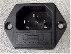
In my circuits, I hav omitted the fuse from the circuit board. It is integrated as a part of the power entry module on the chassis. I prefer to do it this way as the fuse is available externally to the chassis. That is entirely my own preference, so you can do as you wish. I get these modules from our local parts house Torrance Electronics for about $2.
A parts list for a single high voltage supply is as follows:
| Description | Qty | Source | Each | Total |
| 4.7nF 500V Film Cap | 10 | Mouser 871-B32671L472J | 0.27 | 2.70 |
| 1N4007 1000V Diode | 10 | Mouser 583-1N4007B | 0.05 | 0.50 |
| 3.9K 1/4W Resistor | 1 | Mouser 660-CF1/2CT52R392J | 0.32 | 0.32 |
| 11M 1/2W 3500V Resistor | 2 | Digikey PPCHHJ11MCT-ND | 0.49 | 0.98 |
| 115V/230V Transformer | 1 | Mouser 553-FP230-25 | 11.99 | 11.99 |
| 2 Pos Terminal Block | 3 | Mouser 571-7969492 | 0.60 | 1.80 |
| Perf Board | 1 | Radio Shack 276-1936 | 3.49 | 3.49 |
Remember that for a stereo pair, you would need to have 2 HV Supplies.
I expanded upon this high voltage supply to include a sensing circuit that detects when an audio signal is present, then turns on the power to the transformer. Many people keep their high voltage supply on all the time, but for a couple reasons, I chose to have my supply turn off when there is no audio.
- When the panel is charged all the time, it attracts dust.
- When small children visit there is much less of a shock hazard
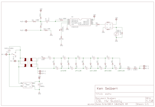
(Click for a larger view.)
In this circuit, the input is clamped by a couple of diodes then fed to a Cypress PSoC microcontroller. The PSoC samples the input, then when a signal is detected, a relay is closed, powering the transformer. A low power (2W) supply keeps the circuit active awaiting an audio signal. The PSoC will keep the transformer powered for 10 minutes after the audio signal is no longer detected. This is to keep the power from shutting off inadvertantly during extended quiet passages.
A parts list for this autosense high voltage supply is as follows:
| Description | Qty | Source | Each | Total |
| 0.01uF 300V AC Cap | 1 | Mouser 72-VY2103M63Y5UG63V0 | 0.24 | 0.24 |
| 4.7nF 500V Film Cap | 10 | Mouser 871-B32671L472J | 0.27 | 2.70 |
| 1000u 10V Electrolytic Cap | 1 | 647-UVZ1A102MPD | 0.33 | 0.33 |
| 1N4007 1000V Diode | 10 | Mouser 583-1N4007B | 0.05 | 0.50 |
| RS1B Diodes | 1 | Mouser 583-1N4007B | 0.22 | 0.22 |
| 1N4148 Diodes | 2 | Mouser 78-LL4148 | 0.10 | 0.20 |
| Solid State Switch | 1 | Mouser 849-CPC1017N | 1.05 | 1.05 |
| Cypress PSoC Microcontroller | 1 | Mouser 727-CY8C24123A-24PXI | 2.40 | 2.40 |
| LED (Optional) | 1 | Mouser 604-WP1503SRD | 0.20 | 0.20 |
| 5V 2W Power Supply | 1 | Mouser 919-RAC02-05SC | 12.78 | 12.78 |
| 1K 1/8W SMD Resistor | 2 | Mouser 71-CRCW0805-1.0K-E3 | 0.08 | 0.16 |
| 100R 1/8W SMD Resistor | 1 | Mouser 71-CRCW0805-100-E3 | 0.08 | 0.08 |
| 100K 1/8W SMD Resistor | 2 | Mouser 71-CRCW0805-100K-E3 | 0.08 | 0.16 |
| 3.9K 1/4W Resistor | 1 | Mouser 660-CF1/2CT52R392J | 0.32 | 0.32 |
| 11M 1/2W 3500V Resistor | 2 | Digikey PPCHHJ11MCT-ND | 0.49 | 0.98 |
| G5LE Relay | 1 | Mouser 653-G5LE-14-DC5 | 1.08 | 1.08 |
| 115V/230V Transformer | 1 | Mouser 553-FP230-25 | 11.99 | 11.99 |
| 2 Pos Terminal Block | 4 | Mouser 571-7969492 | 0.60 | 2.40 |
| Circuit Board | 1 | Email if Interested |
Here is a photo of an assembled board:
Again, I sprayed the back with the insulating varnish to reduce the chances of corona discharge.