|
Projects
|
Projects Welcome To KenSeibert.Com Audio
The electronics box on the back of the speaker does the following:
- Provides a High Voltage source for the diaphragm
- Steps up the audio signal to provide sufficient voltage to drive the stators
- Provides a weighted counterbalance and strong base for the tall, thin ESL panel.
The ESL HV Supply page provides information on the high voltage source, so we won't go into that function further here.
I mounted everything in a heavy-duty aluminum electronics chassis that I purchased from DMS Engineering for about $40 from Ebay. Two of them plus shipping came to about $112, and they arrived in a couple of days. I am happy with the quality of the chassis.
RC14B DIY Aluminum Electronics Project Enclosure Hobby Box Case 12"X12"X3.5"
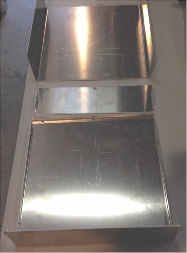
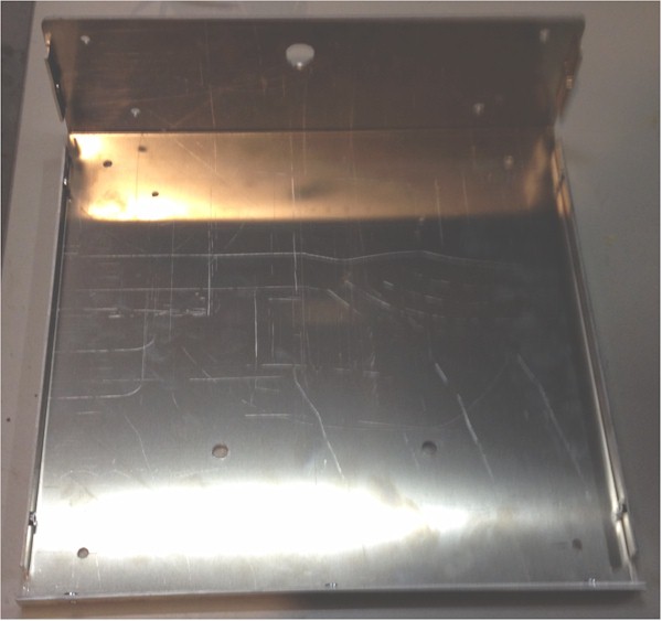
The chassis separates into 3 major pieces. The bottom and back are one piece, the top and sides are another and the front detatches for easier metalworking. Here are a couple photos showing the case together and apart.
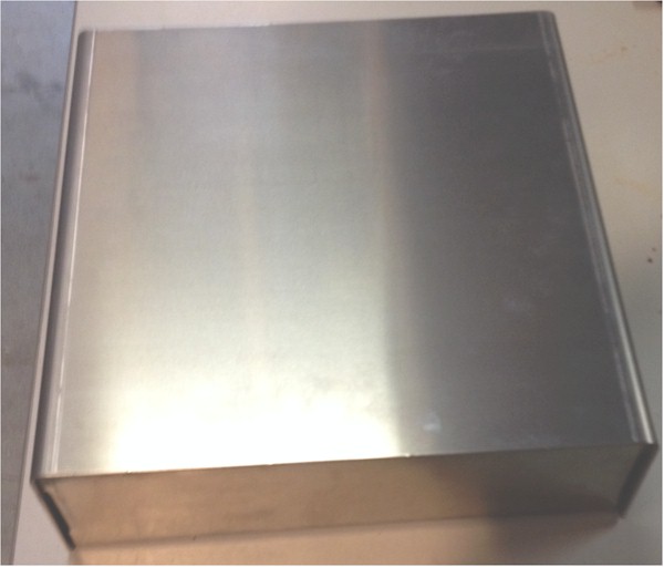
Since in this case, the major metalworking will be on the side that is away from the ESL panel, I'll use that for the "front", even though it is in the back of the speaker assembly.
The components we will mount inside the enclosure are:
- Two setp-up transformers
- The High Voltage Supply
- A terminal Strip
On the bottom of the enclosure we will mount:
- 4 Rubber Feet
On the removable panel we will mount:
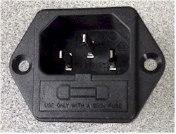
- A Power inlet module
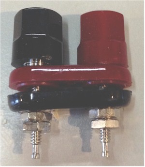
- A set of binding posts
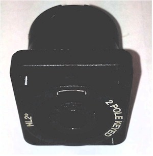
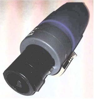
- a Speakon connector
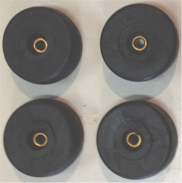
Lets start with the rubber feet. I like these large medium-firm rubber feet from All Electronics. they are Part Number RF-615 and cost $1.80 for a set of 4. They come with an integrated brass bushing meant for a #8 machine screw which make installation easier. Drill a hole for each foot, 1" from each edge near the corners
Next, the transformers. There are several transformers you can use for this purpose. They are 230V primary (sometimes 115V + 115V) with dual 6V secondaries, rated at about 50VA.
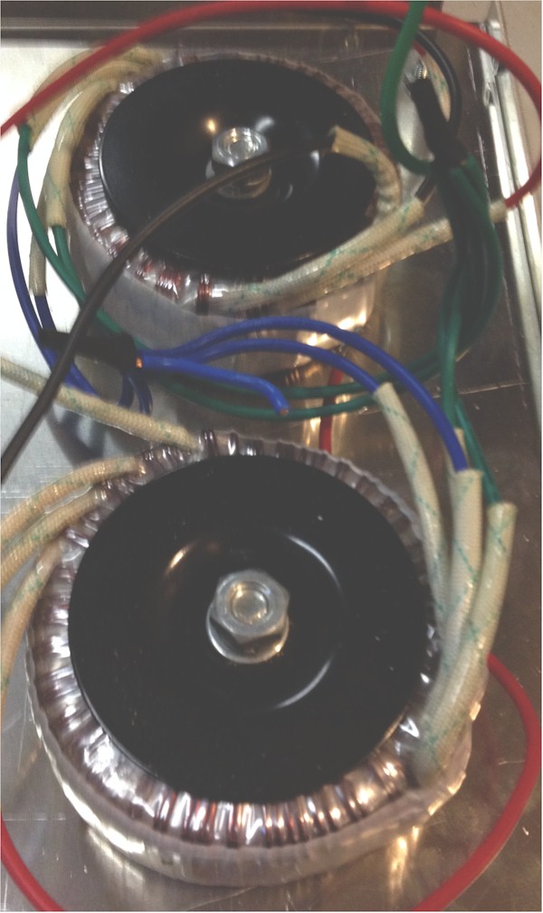
The ones pictured here were made by Antec, however since their factory fire, this model has been discontinued (which is a shame, really, since these were dirt cheap and sound great). Here are a few types you can order now. They are listed in order of my personal preference as to how they sound.
- Antek AN-0506. These are the ones I use that have been discontinued. Try Antek to see if they are back in production. They were about $14 each. The AS-0506 has an internal inter-winding shield that makes them unsuitable for use.
- Triad VPT12-4170, available from Mouser in the USA for about $30 each and they are generally in stock.
- MULTICOMP MCTA050/06, available from UK stock at Newark Element 14 for about $30 each.
On Charlie's Jazzman page, he lists two additional transformer choices.
- Vigortronix 88-5190 (his favorite) available at Rapid for GBP12 each ex VAT
- A set of 4 of the Antek AN-0206. They are $11 each but as of this writing (April 2014), these are sold out.
We want to mount these close to the removable panel, as far from the ESL panel as possible. These transformers are heavy and we want to have that weight away form the ESL panel to counterbalance the height and weight of the panel. This will help keep the panel standing vertically and give it some stability. The transformers come with mounting hardware which usually consists of a machine bolt, a couple of concave metal discs and a couple of rubber pads. Place one rubber pad on the metal surface of the chassis, then the transformer, then another rubber pad and finally the metal disc. The rubber pads protect the windings from shorting out to the chassis or the metal disc. Tighten, but do not over-tighten the nuts to secure the transformers in place.
The key to using these power supply transformers (instead of purpose-built ESL transformers that cost hundreds of $ each) is wiring them up as step-up transformers instead of step-down transformers. We will use the 6V secondary windings wired in parallel as our primary. We will then use the single 230V primary (or the two 115V primary windings in series) as our secondary. This gives us a step-up of about 40:1. This is not enough to sufficiently drive our ESL panels, so we will hook up two transformers to give us 80:1 step-up.
All-important in this is to pay close attention to the winding orientation. All the 6V windings should be in parallel. In my case, these are the blue and green wires. All the blue are tied together and all the green are tied together. The other windings are tied in series. In my case, these are the red and black wires. The drawing below shows how this should be wired:
![]()
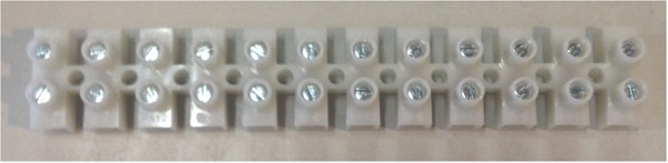
Next we install a small terminal block in the box to allow connection of the staors to the transformer wiring. I like the eurostyle barrier strips, and get mine from All Electronics. It is about $3 for a strip with 12 positions. I just cut off two of the positions to attach using the center hole with a #6 machine screw.
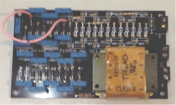
Finally, install the power supply. Please note that the one pictured here is an older version of the one I describe on the power supply page. I have painted the back with insulating varnish. This is the stuff sprayed or painted on transformers and inside electrical panels. One source is Zoro Tools, about $5 a can and it comes in a few different colors.
http://www.zorotools.com/g/00058374/k-G1811056/
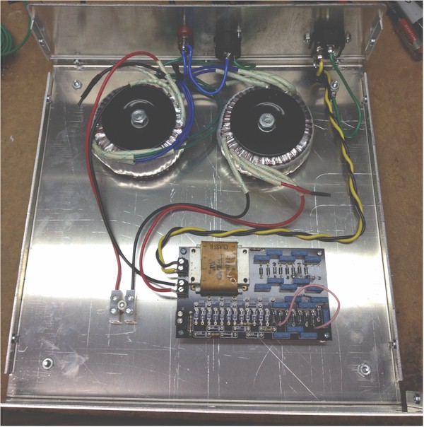
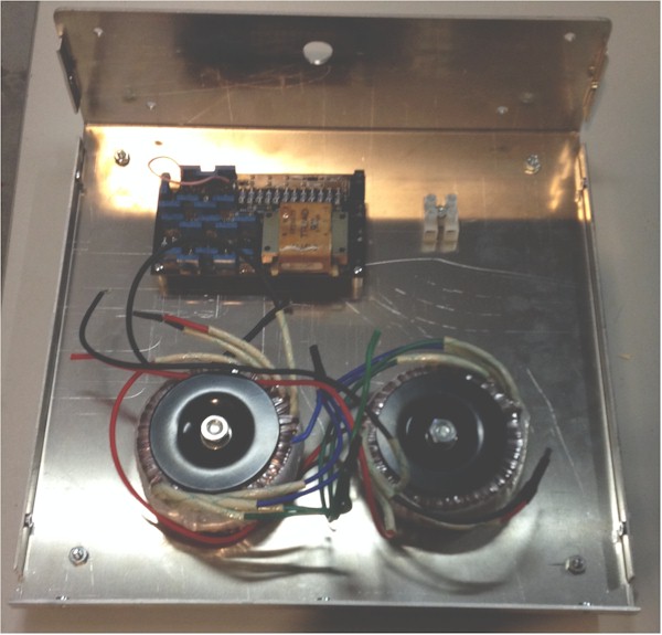
The photos below show the case with the mounting holes drilled, then the parts installed.
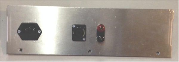
The removable panel has to be drilled and machined to accept the components. I mount three components on the panel, two for audio input - traditional binding posts and a Speakon connector - plus an AC mains power input module. I realize that using both binding posts and a Speakon connector is like belt and suspenders. I have been using Speakon connectors for a few years now, and really like them, but if I give these speakers away to someone else (after I make even better ones) they may not have access to Speakon.
I am not much of a metal worker, so my attempts are pretty crude. I traced the outlines of the components in the panel then drilled pilot holes. I used a nibbling took to get them to the right shape, then filed the edges to make them smooth. Not particularly elegant, but it worked with the tools I have available.
I got the binding posts from Torrance Electronics because they are close and the posts were high quality and only about $2. You can get them at just about any parts house.
The Speakon connectors were purchased from Mouser. I am using the 2 pole version made by Neutrik. It is Mouser Part Number 568-NL2MP and goes for about $2. They always have many in stock. The mating connector is also available from Mouser. It is Mouser Part Number 568-NL2FX-POS and goes for just over $4.
In my circuits, I hav omitted the fuse from the circuit board. It is integrated as a part of the power entry module on the chassis. I prefer to do it this way as the fuse is available externally to the chassis. That is entirely my own preference, so you can do as you wish. I get these modules from our local parts house Torrance Electronics for about $2.
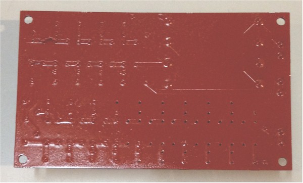
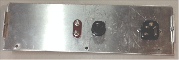
Please note that there are some holes on the fixed panel. The 4 smaller holes are used to affix the chassis to the ESL panel. The larger hole is to allow the wires from the diaphram and stators to pass through into the chassis.
Assemble the removable panel back onto the chassis bottom before continuing the wiring.
Now it is time to wire the components in the chassis. The first step is to wire the transformers to each other. Use the wiring diagram above. If your wires have a different color code, substitute the colors for those in the diagram to help you keep things straight. Connect the transformer wires going to the stators to the two terminal strip connections.
The Binding posts are then wired to the Speakon connector (if you are using both), then wired to the two leads of the transformer that are the audio input. The Speakon connector is labeled on the back for + and - connections.
The power entry module shold have three wires coming off of it. A chassis ground, a hot wire and a return. Conventionally the ground is green, the hot is black and the return is white. Attach a ring contact to the green wire and use the closest foot screw to attach the ring to the chassis. The other two wires are twisted and connected to the power supply AC connector. I was out of white wire and used yellow. Be sure to insert a fuse into the power entry module. This one uses 20 x 5 mm cylindrical fuses, but yours may be different.
Now the electronics box should be fully completed.