 |
Projects
|
Projects Welcome To KenSeibert.Com Audio
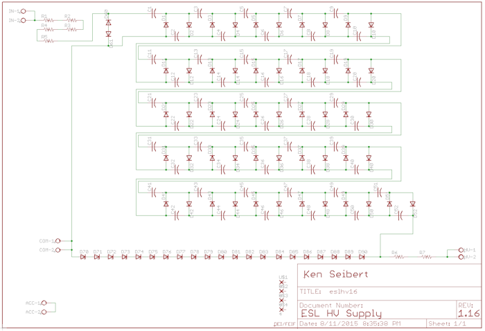
Let's take a look at the schematic as a whole, then discuss each of the parts. You can click on the schematic to see a larger version instead of squinting at the tiny one below.
In an ESL there are some step-up transformers that boost the audio signal by a factor of 80:1 give or take. We are going to tap off of that boosted signal to generate the bias voltage. First, let's get our assumptions out there:
- We need to design for a fairly quiet listening level - the point where the volume is low and the audio signal is also low. Let's assume that at a low level, the amp is driving 1.5V peaks.
- Let's also pick a bias voltage for the diaphragm. In my speakers I wanted 5KV, others typically use 3-7KV.
- We also need to allow for a high audio voltage when the speakers are being driven hard. A 200W amp will typically use rail voltages of 50V, so lets assume a strong signal that is not being clipped will be 45V peak.
The basic principle of this and other HV power supplies is the voltage doubler circuit. The circuit in the diagram below shows a traditional 120V to 230VAC transformer going into a rectifier circuit. If you consider a typical rectifier circuit, the voltage at point A would be roughly 1.414 * the input voltage. 1.414 times 230VAC gives us roughly 325VDC at point A
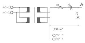
We can expand on this circuit by adding an additional diode and capacitor. On the opposite half of the AC waveform, Capacitor C1 holds the 325V of point A while the voltage swings on the opposite side of the diode, D1, charging C2, through diode D2. When the voltage swings back, the bottom of D1 is at the high point, and with C2 charged, point B is now at about 650V, doubling the voltage.
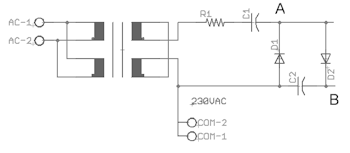
Multiple pairs of diode and capacitor can be added to make a step-up ladder. With 4 diodes and capacitors the voltage is increased by a factor of 4. With 10 diodes and capacitors the voltage is increased by a factor of 10, and so on.
Our first assumption is that the low listening level has 1.5V peaks. This is then stepped up through the 80:1 ESL transformer making 120V peaks. It is this signal we will feed to the multiplying ladder. From our second assumption, we want to have 5000V on the output. This means we need at least 5000 / 120 = 42 steps in the ladder. In the schematic, the ladder is the large central portion of the circuit. I have included 52 steps in the ladder for some extra headroom.
What happens when the listening level is higher then the low 1.5V level? In that case, the voltage going to the ladder is higher and the multiplied output voltage will be higher. To keep the output voltage in the 5000V range, the high voltage is then clamped at 5000V by a string of zener diodes. These are D70 through D90 at the bottom of the schematic. The actual clamp voltage is determined by the zener voltage and the number of diodes. I use all 21 of the diodes at 200V each for a final clamped voltage of 5200V.
What happens when the amp is driving hard? Our third assumption is that the maximum audio voltage will be no more than 45V. When put through the 80:1 ESL transformer, this will give an input voltage of 3500V. Putting that kind of voltage into the ladder will fry the components, so we have to limit the input. Zener diodes D60 and D61 clamp the input to 200V max.
If we are driving 3600V into a 200V clamp, this will generate significant current in the clamping diodes. To protect the diodes (and the rest of the ladder) we will put current limiting resistors on the input. R1 to R5 provide this limiting. These are 1W surface mount resistors of 100K Ohms each.
Finally, the output voltage needs to be sent through a large value resistor (10M-100M Ohms). Since the voltage there is high, we use two resistors in series to each handle half the voltage level. These are each 3500V 10MOhm resistors.
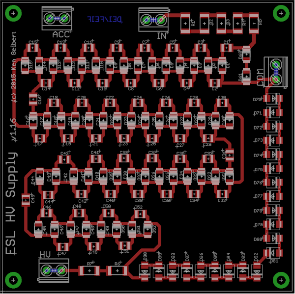
Layout
The board was designed using all surface mount components allowing a compact design. The board is less than 4" square yet contains over 100 components. All connections to the board are via screw terminals, or if desired, the terminals can be omitted and wires soldered directly to the board. Below is the board layout (done in Eagle CAD).
The Bill of Materials with part numbers from Mouser and pricing:
If you are interested in purchasing these boards, either the bare board or a completed unit, send me an email. The bare boards are $10 each with completed and tested boards at $45 each. The completed boards are built to your voltage specifications.