 |
Projects
|
Projects Welcome To KenSeibert.Com Audio
To help you gather the items required for Final Assembly, there is a parts list at the bottom containing the items, sources and pricing.
The overall design that I finally settled upon was to have the panels mounted in aluminum channel rails. At the top are the resistor boards which will be enclosed in a vented cap. At the bottom below the panel will be a place to hold the electronics.
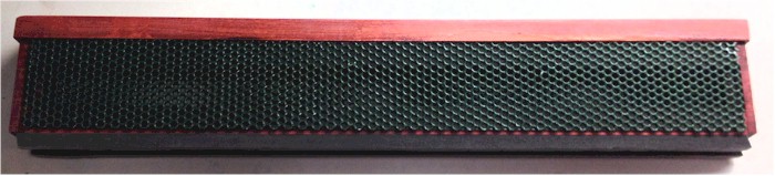
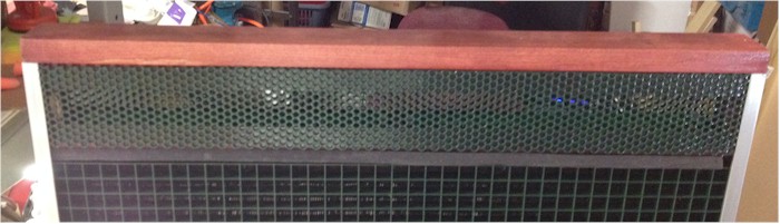
The Vented Top Cap
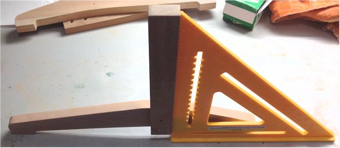
I have limited skills and tools for wood working, so I try to piece together wood items that I can purchase from Home Depot with minimal cutting involved. The cuts I do make, I try to have them be simple square cuts I can make with a band saw or similar. To make a vented cap, I am using two pieces of perf metal that used to be a small perf metal stator panel. To provide a framework to hold these metal vents, I have glued together 1/4" thick slats and some 3/8" square wood dowels. The slats are 1 1/2" wide, which just fit inside the aluminum channel. The photo below shows the detail on how these are assembled so they fit over the resistor boards.
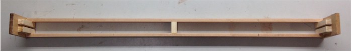
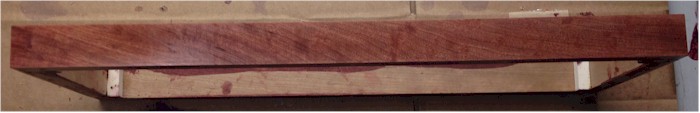
On the top of the cap is glued a 1-1/2" wide board that fits inside the aluminum channel, then right on top of that a 1-3/4" wide board that fits over the channel. This makes a good looking top piece. The wood pieces are sanded, stained and clear-coated for looks.
The channel is drilled and countersunk so that screws can be used to hold the channel together to the wood cap, providing structural integrity to the top.
Between the two aluminum channels is an open area. One of my earlier perf metal ESL experiments was cannibalized to use the perf metal for vent covers. These are trimmed to 3" x 22-3/4", then the edges filed smooth and the paint touched up. These were affixed to the top cap using 1/32" thick foam tape.
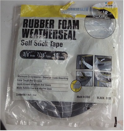
Some foam weatherstripping is affixed to the bottom of the cap to aid as a cushion against the louver panel.
I got the weather stripping from Home Depot a long time ago for a home repair project. I don't remember how much it cost, but it was not expensive.
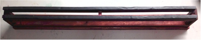
The Hollow Bottom Cap
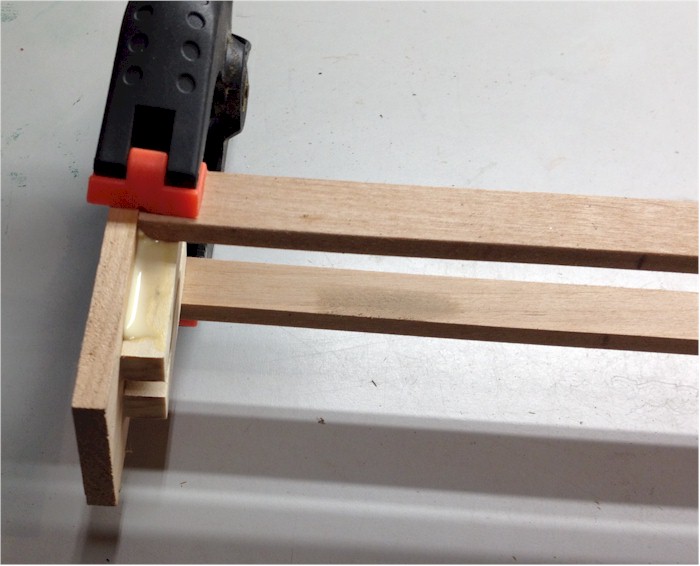
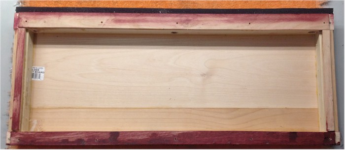
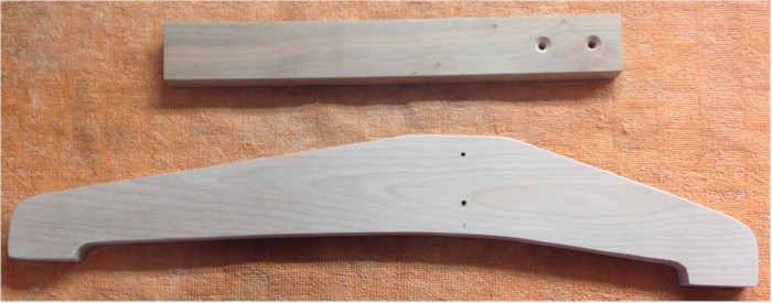
The electrical panel will mount on the bottom of the assembly, on the back. To dress up the front of the assembly as well as have a place to hold the electronins, we will make a hollow panel for the bottom. We will start with 2 strips of good hard wood. In this case I'm using maple. We want hard wood here because the heavy electrical panel will screw onto this and we want a sturdy point of connection. Then we will use a couple 1/4" thick wood slats to make the overall width of the box come out to 9". The maple is 1-1/2" wide so that it just fits inside the aluminum rails. We will glue these together:
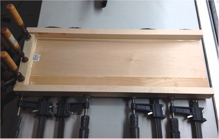
On the ends of the box I glued 1"x1" strips, then 1/4" thick slats to make up the 1-1/2" height of the maple. If I had a table saw and could rip a piece of wood the right thickness, I would have done that, but I don't, so I make do with what I have.
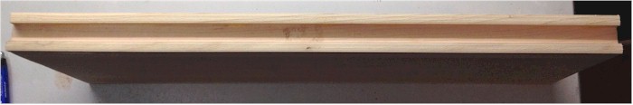
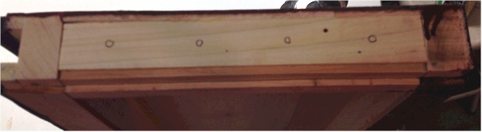
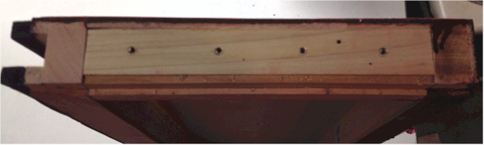
The top side of the box will abut the bottom of the stator panels. The bottom of the stator panels have a short section of TIG rod that extends beyond the panel where the segments are soldered together. We need to have a provision for the stator panels to rest on the louver and not on the TIG rods. To do this, I glued two 3/8" square strips to the top edge of the box. This will make room for the TIG to hang in the open space created. If I were a real woodworker, I would have just used a dado blade to make the groove.
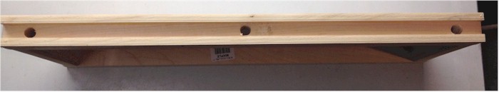
Also coming out of the bottom of the stator panel are the leads connecting to the front and back stators as well as the high voltage leads going to the charge strips. I drilled three holes in to the top of the box to accept these leads.
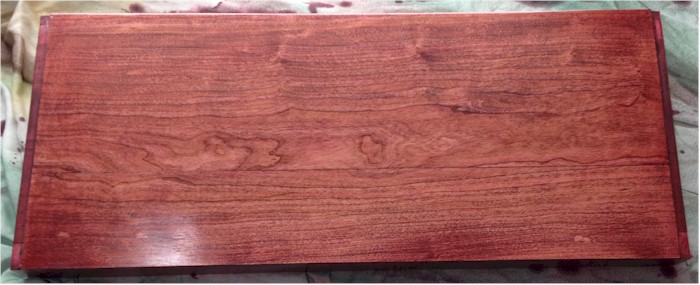
The bottom of the box is exposed to viewing. To dress up this section, I glued on a thin slat of cherry wood (1/8" thick).
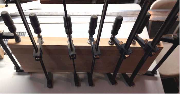
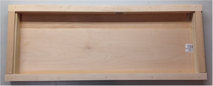
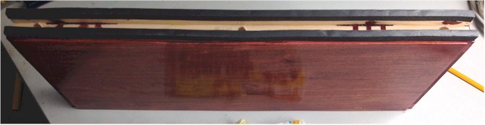
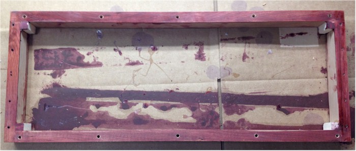
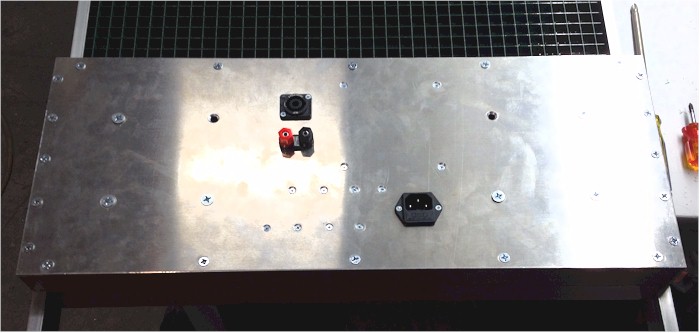
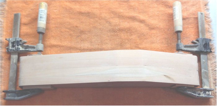
On the back of the box, the electronics panel will bolt to the aluminum rail, then screw into the maple to attach. As the box is now, it slides into the rail. This leaves a gap of the channel wall thickness between the wood and the back of the rail. To make it flush, I glue on 1/8" thick strips on the areas that will not be covered by the rail. I use the rail as a guide, then glue and clamp the strips to the wood area that is exposed.
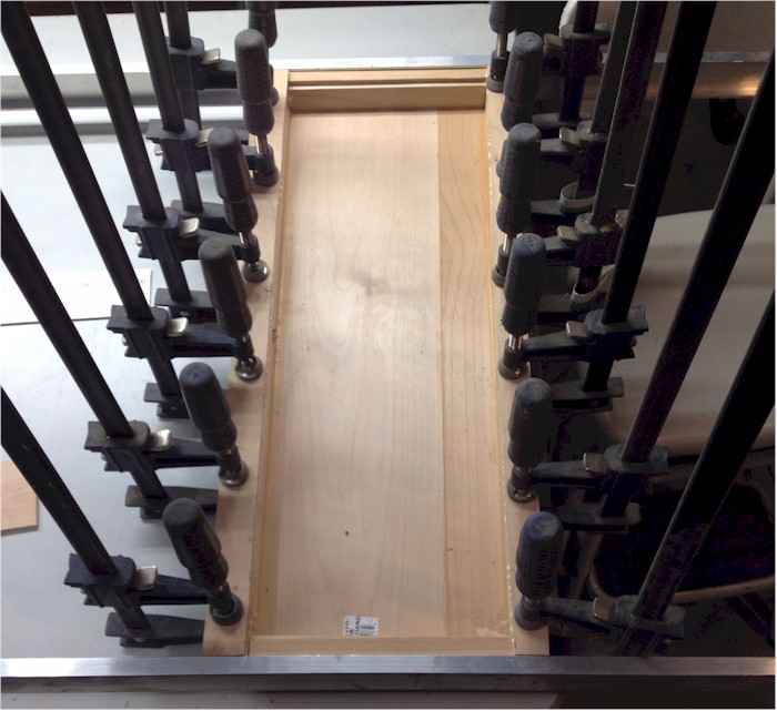
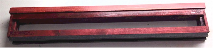
The front of the box is also viewable in the finished product, and is is recessed into the rail. To solve both of these issues, I glue on more of the 1/8" thick cherry slats to cover the front area between the rails. Then the entire assembly is sanded smooth with successively finer grit sandpaper.
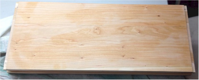
The surface is wiped clean of sawdust using a soft cloth lightly moistened with mineral spirits, then the cherry portions are stained and buffed. I am choosing a cabernet stain to bring out the cherry character.
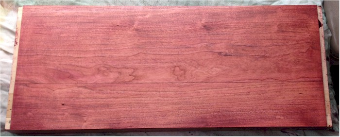
Next I'm using a few varathane coats with fine sanding between to give the cherry a deep gloss finish.
The final touch is to apply the weatherstripping to the portion of the rails that will contact the stator panel.
The aluminum channel is cut to length, in this case 63", then the bottom is drilled and countersunk. The holes are drilled so as not to interfere with the screws which will attach the electrical panel to the back. The channel extends beyond the bottom of the box. This is the point that the legs will attach later.
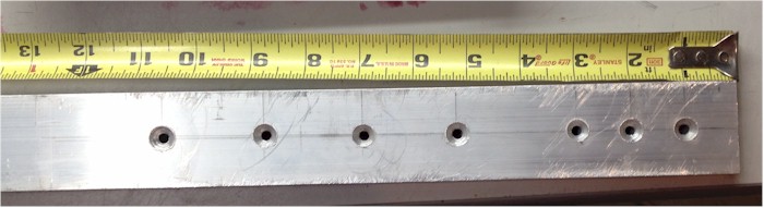
The top of the bottom box starts at 50" from the top. This is measured out and the holes are traced onto the box. Pilot holes are then drilled into the sides of the box.
The electronics panel is deeper than just the depth of the bottom box, so we need to makle an extension box for it. I used 3/4" x 1-1/2" cherry for this so that it matches the rest of the woodwork.
Once everything was the right size, I glued and clamped it. I used short pieces of the 1/2" square material as corner gluing blocks for added strength.
After the glue dried, I gave it some stain to match the rest of the woodwork.
Then gave it a couple coats of Varathane to make it nice and glossy.
The extension box is attached to the electrical panel by the side screws, so I drilled pilot holes into the cherry box for these. The electrical panel and extension box are attached to the bottom box using the screws on the top and bottom. FOr these I drilled clearance holes in the extension box. then used those holes to position the assembly onto the bottom box to mark screw locations. I then drilled pilot holes into the bottom box for these top and bottom screws.
I then used those holes to position the assembly onto the bottom box to mark screw locations. I then drilled pilot holes into the bottom box for these top and bottom screws.
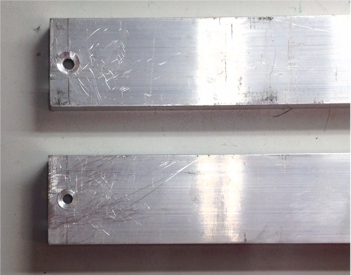
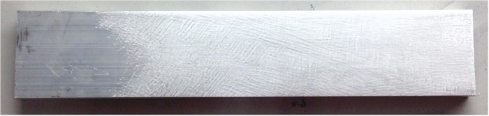
Now, the aluminum channel as it comes from the mill and goes through the supply chain, then after drilling, etc, does not look so good. It has scratches, mill marks, dings, and so on. Here is an example of how the raw channel looks.
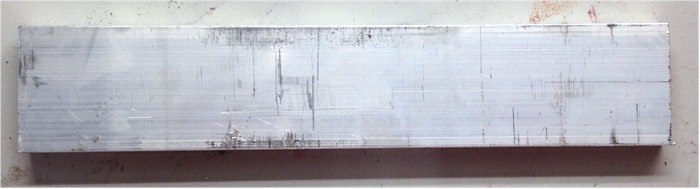
I went over the channel using my palm sander with about a 200 grit sandpaper. On this test piece, I left a portion of the aluminum on the left with the original mill finish so you could see the difference. The orbital sander removed the major marks and scratches but left a swirly pattern.
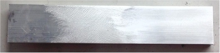
Rubbing the aluminum by hand with a 600 grit fine paper gives the channel a satin look. You can use the edge of the channel as a guide to keep the hand rubbing uniformly straight. This time I only hand finished the portion on the right, so you can see the original mill finish, the orbital sander finish and the final rubbed finish.
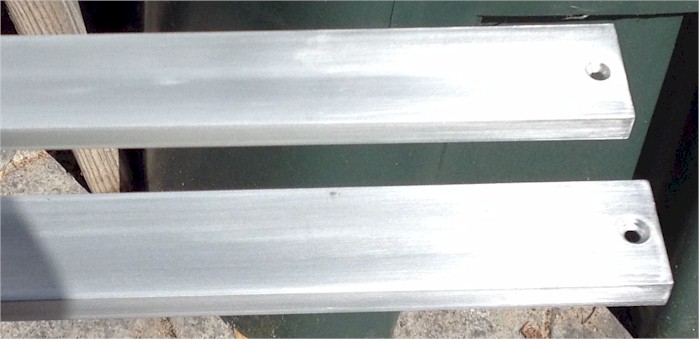
After treating the two side channels this way, I sprayed them with the clear insulating varnish (nothing like bare metal near high voltages). After spraying, they look like this:
Now we will start to put it all together. First, attach the side rails to the bottom box using 4 wood screws on each side. I'm using #10 flat head screws, 3/4" long. I purchased a box of these from a local hardware store many years ago, but you can find them at Home Depot or just about any hardware store. Leave the screws somewhat loose - this will help in the assembly process later.
Next, slide the cap into place, but do not use the screws yet. Use a pencil to mark where the bottom of the cap comes inside the side rails.
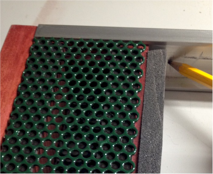
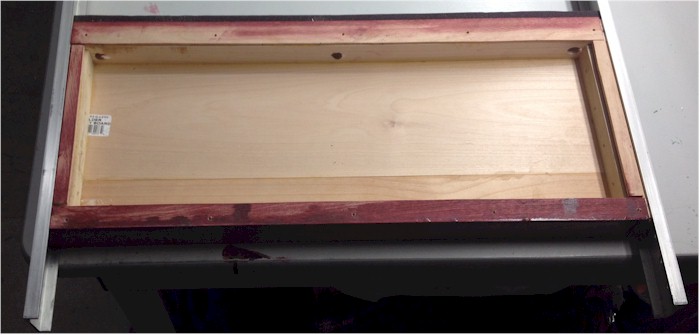
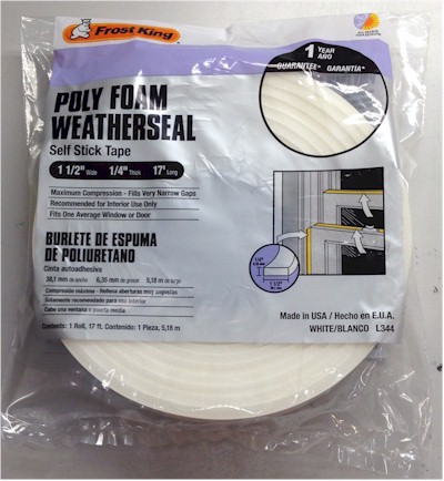
As an extra insulator and side cushion, install some poly foam tape inside the side rails between the mark you just made and the top of the bottom box. Home depot has some cushion tape that just fits inside the channel and is $2 for 17 feet.
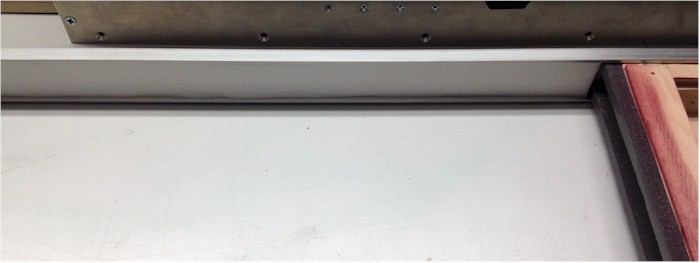
After installing the tape, it should look something like this:
Slide the stator panel into the side rails, feeding the lead wires through the holes in the bottom box. Press it firmly against the foam cushions on the bottom box.
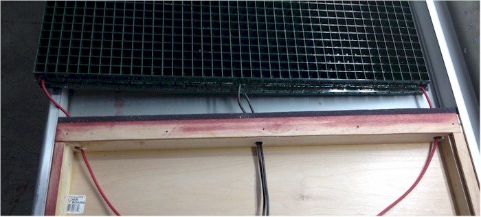
Replace the top cap and screw it into place and tighten the screws on the bottom box. You now have the main framework in place.
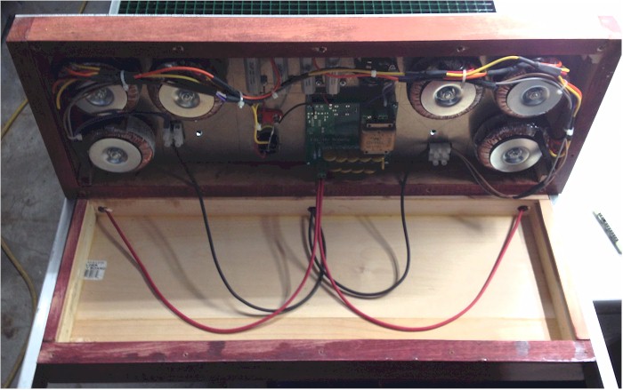
Now attach the lead wires from the stator panel to the appropriate locations on the electrical panel
Then using #10 x 2-1/2" wood screws, attach the electrical panel assembly to the bottom box.
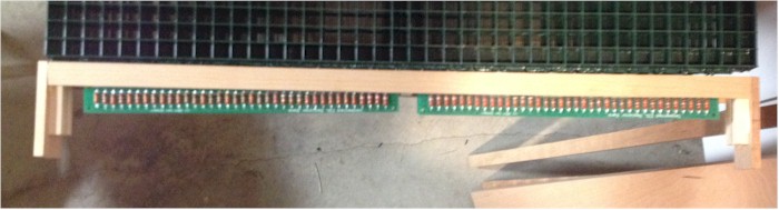
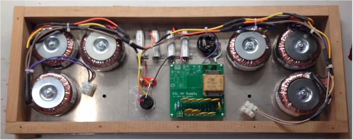
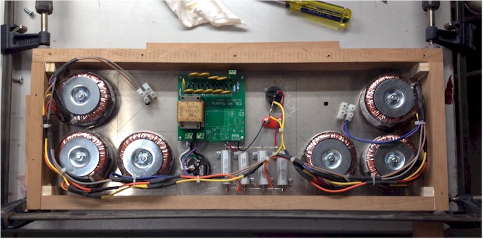
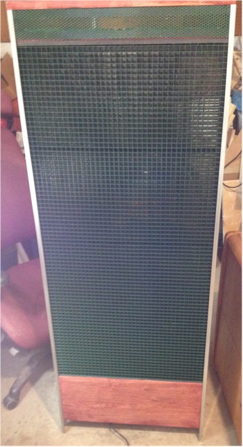
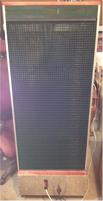
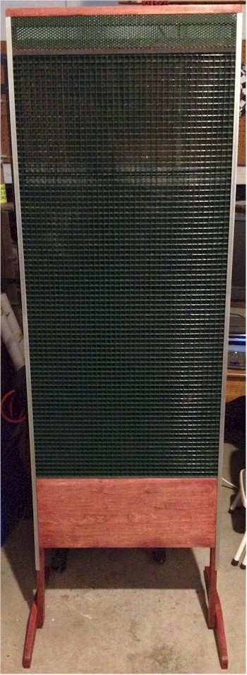
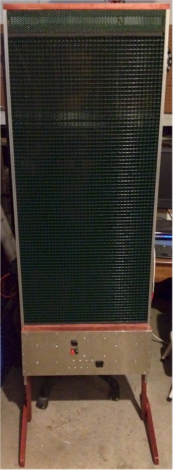
Everything is complete except for the legs to keep the speaker upright. Of course, I had to hook it up to the rest of the audio system to hear how it sounds now. Here are front and back photos of the speaker, minus the feet.
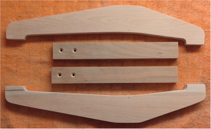
I drew a template for the feet onto some 1/4" MDF>
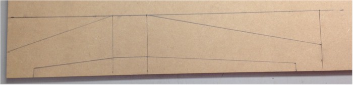
Then cut it out using a bandsaw. You might like to have a different style of foot, shorter, longer, more curvy, etc. This shape appealed to me.
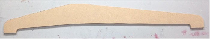
After cutting ot out, I sanded the edges smooth and straight, then used the template to trace the foot outline onto a piece of 1x4 cherry.
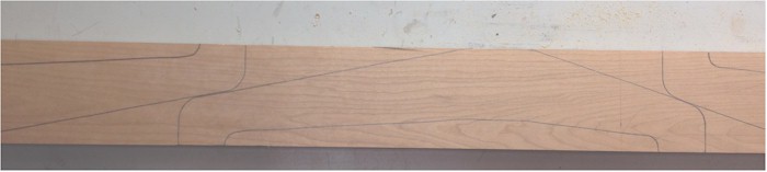
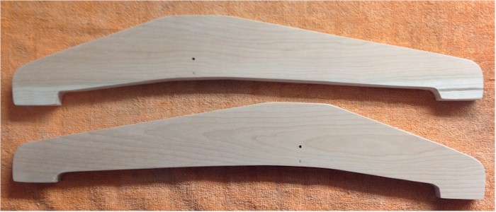
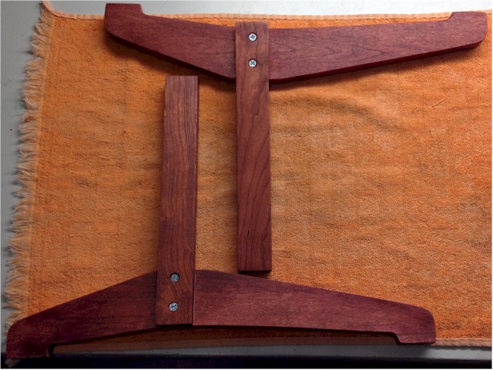
I cut these out carefully using a hand-held jigsaw. My bandsaw was not up to the task with the 3/4" thick cherry. I did all 4 feet at one time since I was on a roll. Once I had them all cut out, I aligned them then clamped them together.
By clamping them together I could file and sand them all at once, keeping their shape identical. I then cut two pieces of 3/4" x 1-1/2" cherry to 12" lengths. These will attach to the feet, then slide into the rails, elevating the speaker about a foot from the floor. You may opt to have the legs shorter or longer to suit. I drilled and countersunk two holes for #10 x 1.25" wood screws into the uprights. Then the 4 pieces were sanded using progressively finer sandpaper until silky smooth.
On the side of the feet facing inside, drill a pilot hole for a #10 wood screw in the center of the flat part, 3/4" from the bottom. Be careful not to drill all the way through
Loosely attach one of the legs to the feet using a single screw.
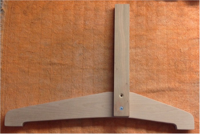
Use a square to align the leg into a perfectly upright position, then use another screw to mark the position of the second pilot hole.
Remove the leg and drill the second pilot hole, again taking care not to drill all the way through.
Touch-up the sanding, then stain the pieces. Sfter the stain is dry, use a little woodworkers glue and re-assemble the feet to the legs.
The legs fit into the side rails where they extend beyond the bottom. Drill pilot holes, then attach the legs to the speaker assembly using #10 - 1/2" screws. Again, take care not to drill the pilot holes all the way through.
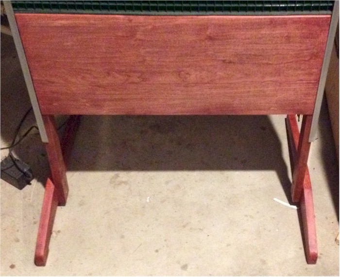
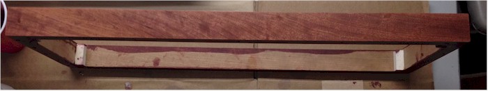
This completes the speaker assembly! Here are photos of the front and back.
Parts List
| Item | My Source | Price | Qty per Speaker | Qty per Pair |
| 1.75" x 0.5" x 0.125" Aluminum Channel, 6ft | Buy Metal | $23 | 2 | 4 |
| 1x2 Cherry, 6ft | Home Depot | $10 | 1 | 2 |
| 1x6 Cherry, 6ft | Home Depot | $31 | 1 | 1 |
| 1x2 Alder, Maple, poplar | Home Depot | $4 | 4 | 8 |
| 1/4 x 1.5 Alder, Maple, poplar | Home Depot | $4 | 5 | 10 |
| 2" x 22.5" Perf Metal | Scrap Box | - | 2 | 4 |