 |
Projects
|
Projects Welcome To KenSeibert.Com Audio
To help you assemble the items required for constructing the stator panels, there is a parts list at the bottom containing the items, sources and pricing.
The Louver Panels
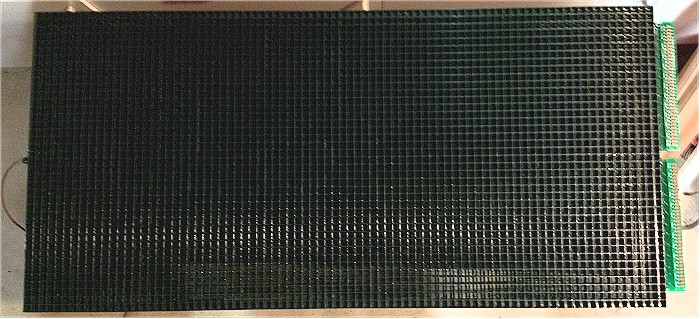
The stator panels are made by affixing TIG welding rod to drop ceiling lighting panels (louvers). This allows the panels to be segmented in any way the user desires. I used grid with 1/2" squares. It typically comes in sheets of just under 24" x 48". This is so they can be dropped into grids spaced 24x48 and allow space for the grid itself.
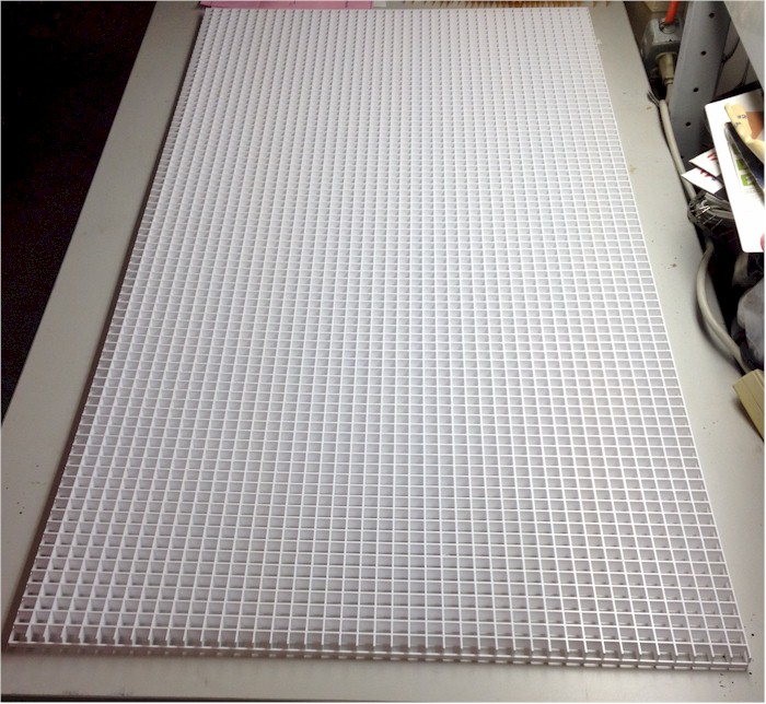
Most home improvement stores sell these louver panels, but you may not want to use those. Many of them are made of styrene instead of acrylic. The outgassing of styrene can weaken adhesives unless it is one specifically made for styrene. Also, most home improvement stores carry louvers that are 3/8" thick. It is hard to find stock of the 1/2" thick material. I'd highly recommend using them. I have used both kinds. On the Home Depot (or Lowes) version I have had to add some TIG rods to the back to stiffen them up. If you take a sample of each kind, the 3/8" ones are easy to flex while the 1/2" ones are far stiffer.
You can get 3/8" acrylic panels at Home depot for about $13. Home Depot Grid Panel
Far better panels can be found at Central Lighting Plastics. These are up to 1/2" thick. They are roughly twice the price at about $25 each
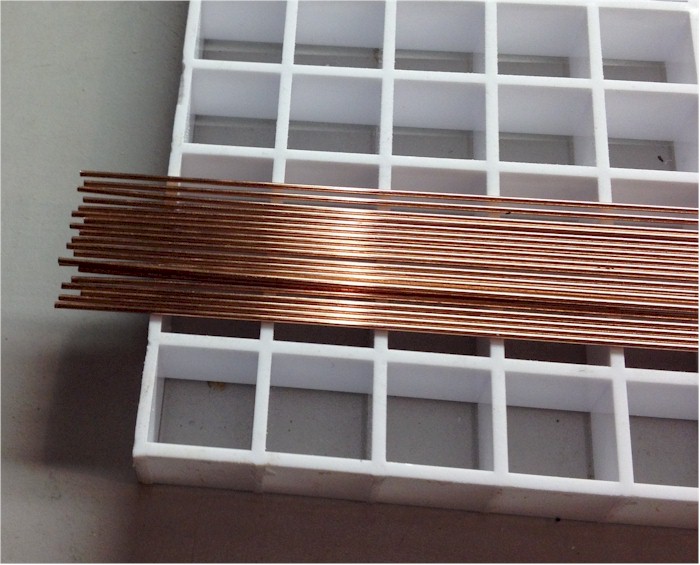
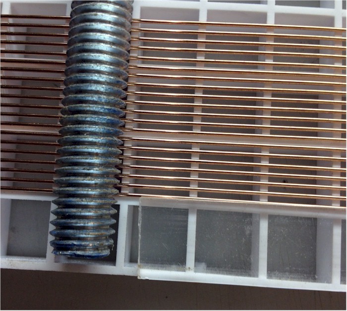
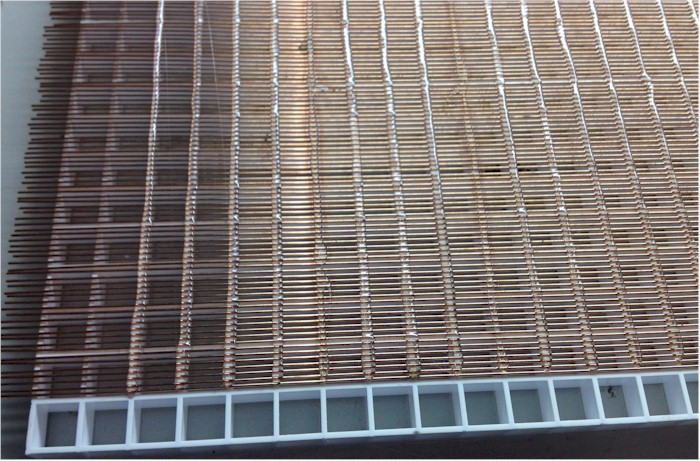
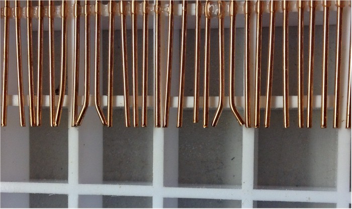
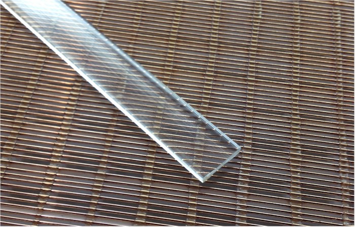
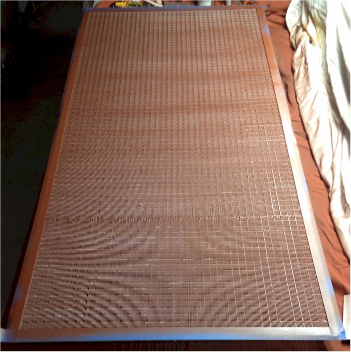
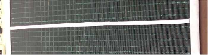
There are some things to note in the photo below. This photo is the 1/2" thick panel in the link above, but the same issues apply to the 3/8" panels as well.
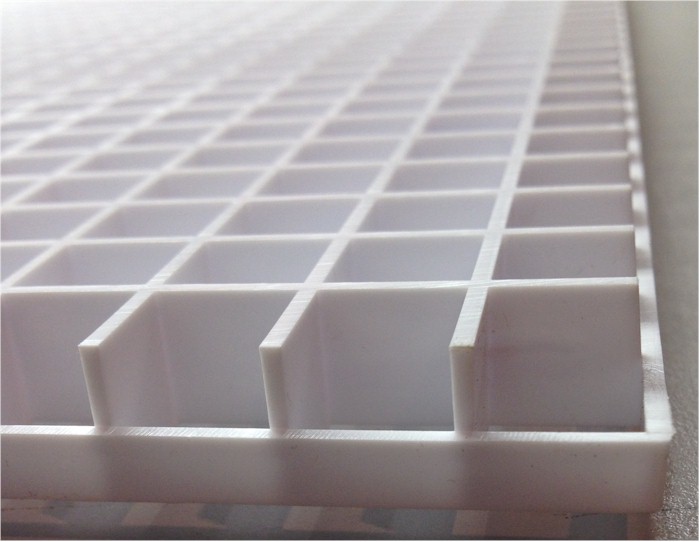
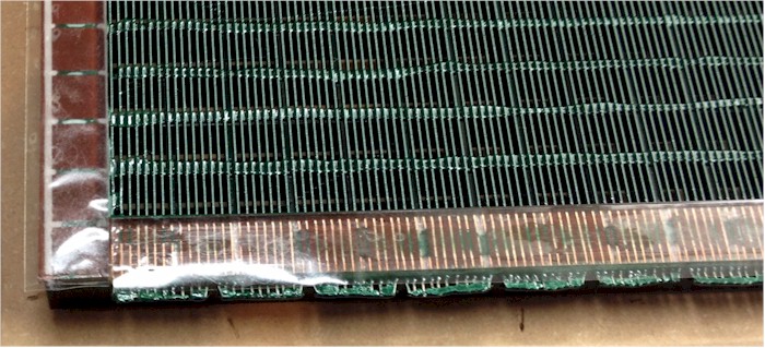
- Half Height Edge - The edges of the panels usually have a half-height grid to allow panels to be joined together seamlessly, so I trim that off using a power jig saw, keeping the blade close to the portion of the panel I want to keep.
- Tapered vanes - If you look closely at the panels, you will notice that the louver vanes are tapered. One side of the panel has a wider louver than the other. You want to have plenty of surface area for the glue to hold, so use the wide side as the side to glue the rods.
Also worthy of note is that the injection moulding process leaves tiny raised points on this side. To keep these points from interfering with the spacing of the rods and to roughen the surface to allow better glue adhesion, lightly sand the panel with some 120-180 grit sandpaper, then clean it off well. I used my palm sander for this as well as cleaning up the edges of the panel where the half-height vane was cut off.
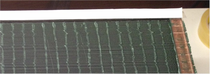
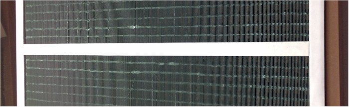
The photos below show the surface and edges of the louver panel after trimming and sanding.
The TIG Rods
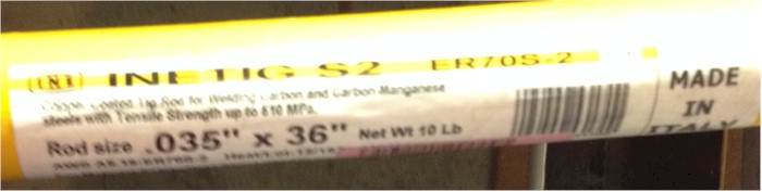
Next comes the TIG rod. You can find a huge selection of rods at just about any welding supply shop. They come in different diameters and different materials. They are normally sold by weight. For my panels, I opted for the least expensive rod that was 0.035" diameter. This turned out to be type ER70S-2. This type was also copper coated which made soldering much easier.
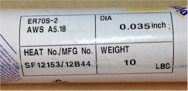
It was about $65 for a 10 pound tube at Gardena Welding Supply. This is enough rod to do about 80 linear inches of 36" long panel. My 4 panels are each 23" wide plus an extra 33% for the difference between 36" rod and 47" panels. This means I need 23" x 4 = 92" plus 33% = 123" of rods. This means I'll need 16 lbs or so of rod. It is less expensive buying two whole 10 pound tubes than just buying the amount I need needed. You can order welding rod online as well.
Here is a link to some on Amazon for about $53 plus shipping.
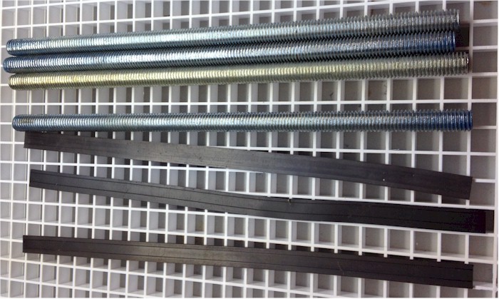
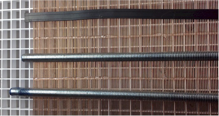
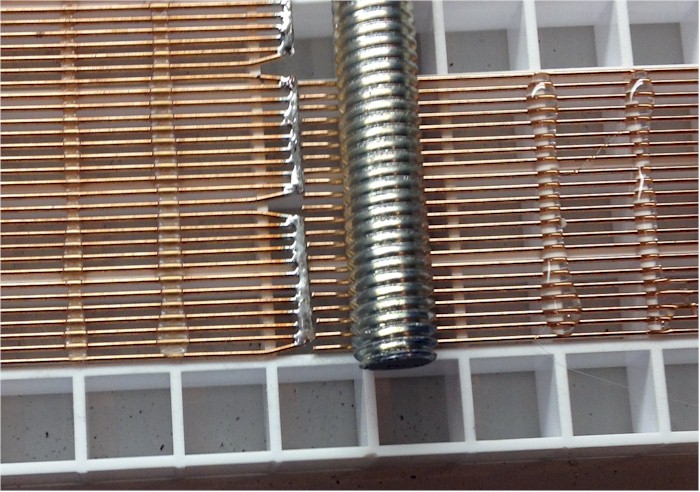
To aid in aligning the rods onto the panel, I purchased a few 1/2" x 13 threads per inch allthread rods from Home Depot for less than $2 each. I then used these rods as spacing guides. A few strip magnets that I had laying around aided in holding the rods in place.
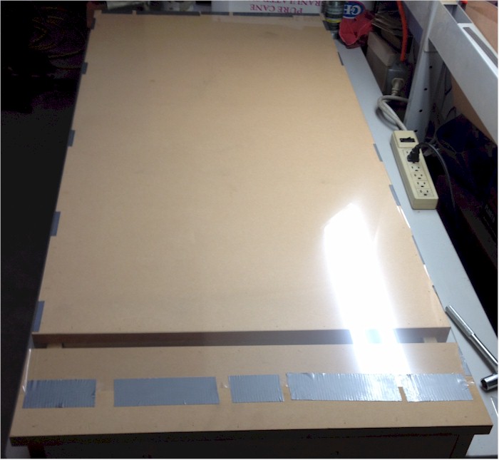
The TIG rods are only 36" long and the panel we are using for this build is 47" long. Also, the rods are only nominally 36" long. They actually vary in length by 1/8" or so. We will have a solder joint in the field of the panel in order to make a 47" long stator. For this reason, we want to clamp the panel in place and clamp a guide board across the panel to where the rods can align.
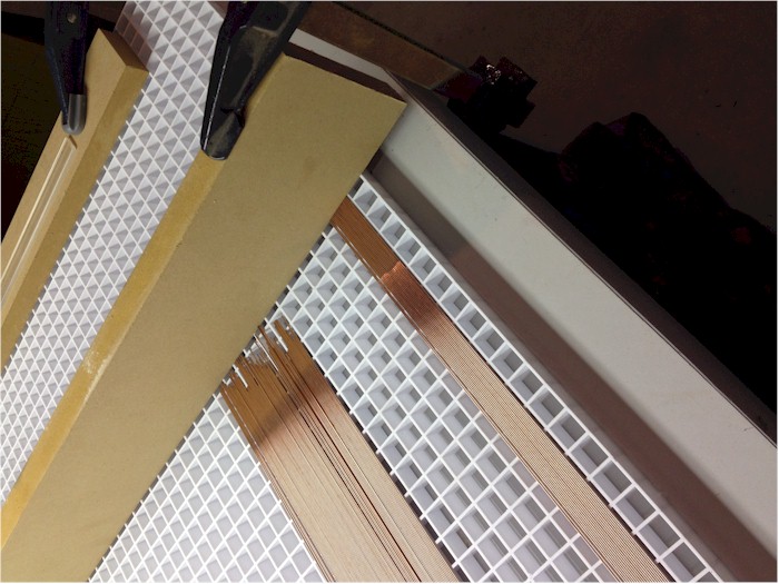
We also want to leave some hanging over the end of the panel so we can make electrical connections later.
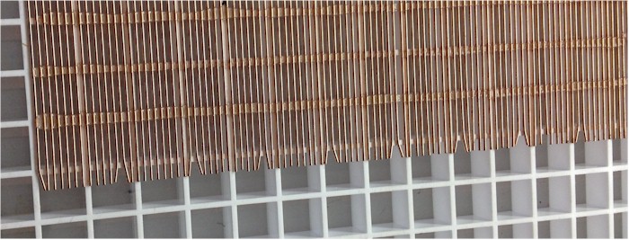
With the rods pushed against the alignment board, start the spacing process at the opposite end. Use a piece of the all-thread to hold the rods spaced properly. I use a small screwdriver to move the rods until they lock into place in the threads, then a strip magnet to hold them there. Only do a couple dozen rods at a time until you get the hang of it.
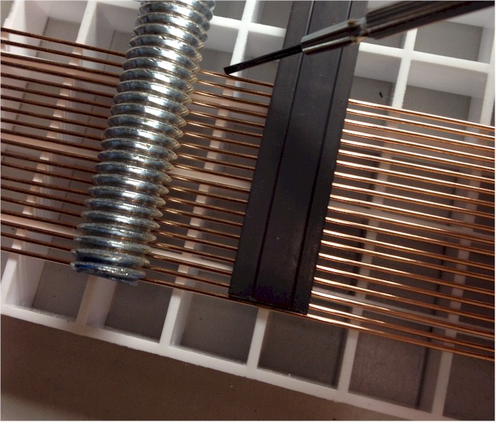
Place another all-thread beside the magnet, then slide it to the right. This will align the rods over a longer distance.
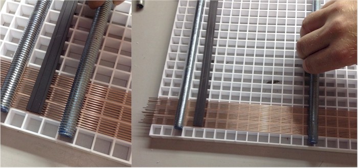
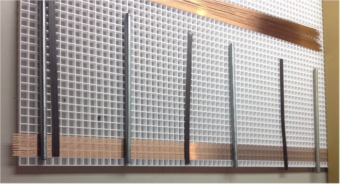
Add another magnet strip to hold that section in place and then use another all-thread to repeat the process aligning more of the length of rods. Continue in this manner until the whole length of the rods is aligned and held in place by the magnets and all-thread.
We will be using some acrylic strips that are 1/8" x 5/8" as spacers to get our stator to diaphragm spacing. For this reason, our stator sections will start 5/8" from the sides. It just so happens that the vanes on the louver are 1/16" wide and 1/2" apart, so we will start the sections one whole grid inside the edge (one space and 2 vanes). You can use a piece of the acrylic to verify your spacing.
Next we want to use some E6000 adhesive to glue the rods to the grid panel.
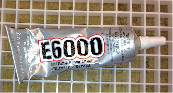
I get the E6000 from Joann Fabrics, although it can be found in many craft stores. It is about $5 per tube and it takes about 2 tubes per stator panel (at least the 23" x 47" stator panels that I made). If you go into the store be sure to print a coupon from their site to get 40-50% off one item. If you forget, they can even scan the coupon from your smart phone.
If you are buying something else at the same time, it can be found Here at Amazon at under $3 per tube.
Run a bead of the E6000 across the rods on top of one of the vanes. Try to stay just on the rods and vanes so that excess adhesive soes not mess up the spacing of the next set of rods or looks too messy. As the glue sets, it will flow over the rods and adhere to the grids, leaving a good flat surface. Put a glue bead across the rods in 5 or 6 places along the length of the rods to make them secure. We will come back later and glue the rest.
I purchased the online rods to continue with this build and found a couple of issues. The rods are usable, but they are not as straight as the rods from my local welding supply (and they are a fraction shorter). I found that in order to have them align properly, I had to have the all-thread and magnets much closer together and could only glue a portion of the rods at a time (until I go out and buy more all-thread). I will not be using that kind again. The Pinnacle brand rods I purchased from the local supply house were much easier to work with and saved a lot of time.
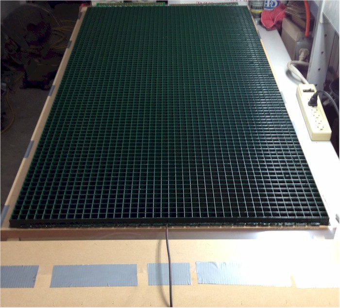
After the glue dries (an hour or so), you can proceed with aligning the next set of rods. Use the all-thread as before to align the rods to each other and to the set of rods that are already on the panel. Repeat the steps above until that set is aligned and glued, then repeat until the panel is filled to within 5/8" of the other edge.
Once the panel has a set of rods across the width go back and run a bead of adhesive across each louver vane, except for the first 2 vanes on the end and the last vane in the middle. We will come back to those two special cases later.
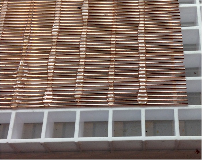
At this point, we should have a panel that has one course of TIG rods across the width.
Segmentation
Now we start to do the electrical segmentation. If your panel is less than 36" long and you use a single length of TIG rod, you can put this step off until later. In our case, we need to do the segmentation now as we will be soldering the rods into segments, both on the ends and in the center.
The rough number of segments can be given by a formula provided by Bolserst on the DIY Audio forum POST #23:
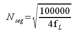
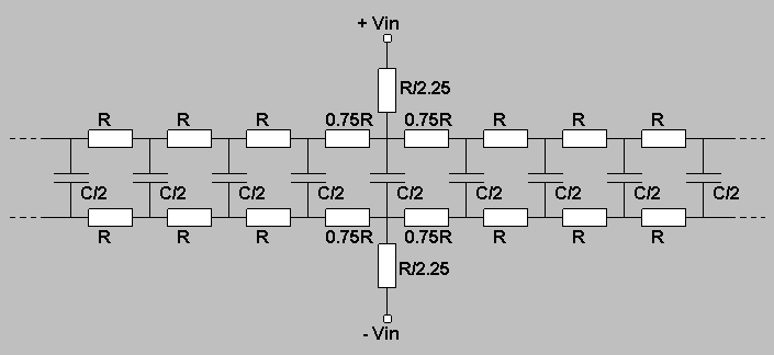
where Nseg is the recommended number of segments and fL if the lowest frequency you expect your panels to reproduce. In my case, this works out to 25 physical segments. Dividing the panel into segments requires resistors between segments so that the resistors in combination with the capacitance of each segment creates an RC ladder filter circuit. There are a multitude of ways to divide up the segments. The one that appeals to me is a symmetric one with all the segments being the same width. The center segment gets a full range signal, then high frequencies get filtered out for each neighboring segment. To create a symmetric setup, you would need an odd number of segments - one in the center, then pairs split between each side.
A spreadsheet available on DIYAudio.com written by Bolserst gives the formulation for the segmentation including the resistor values required. The link to the spreadsheet is in post #67. When putting the number of segments into the spreadsheet, pay attention that the number of segments is the number of electrical segments, not the number of physical segments. Since we are making a symmetrical array, the electrical segments are split between the two halves, so in my case, the 25 physical segments correspond to 13 electrical segments. The following diagram is from that spreadsheet.
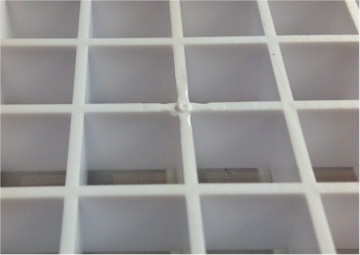
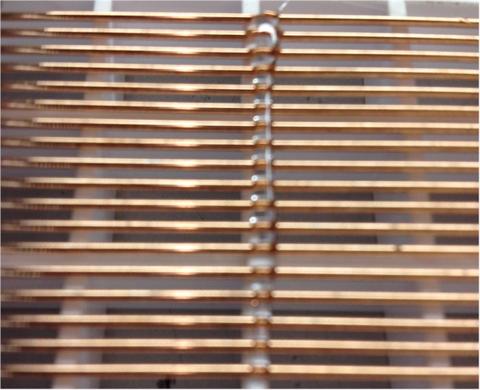
A count of the rods across the width of the stator yields 277 rods. Dividing this up into 25 segments yields 11 rods per segment with a couple left over. We will allow the leftover rods to be added to the edge segments and recalculate the resistor values accordingly. To begin the segmentation process, we will slightly bend the outer two rod ends of each segment inwards. Find the center of the panel, either by counting rods, or by measurement. Since these segments are 11 rods wide, we will count 5 rods on each side of the center to find the edges of the segment. Then slightly bend the rod inwards, as in the photo below:
Repeat this process for the remainder of the segments, slightly bending the rods inwards until all of the segments have been done this way.
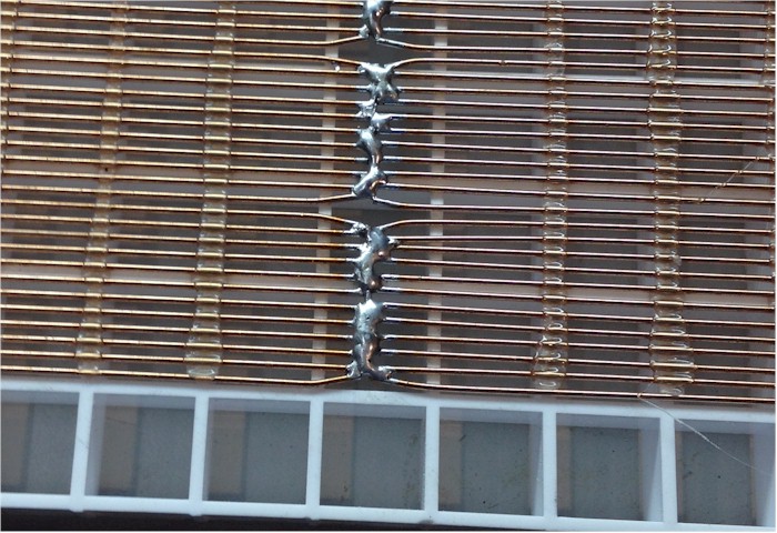
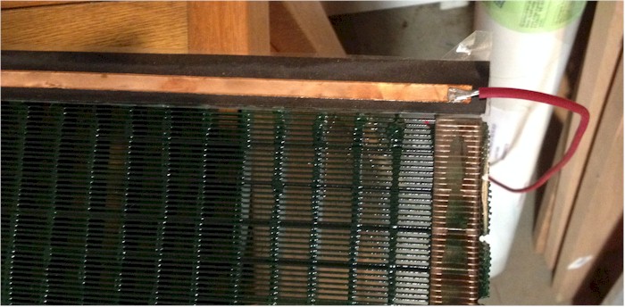
Now, take some 20ga copper wire (20 ga is 0.032" dia, about the same size as the rods) and lay it along the ends of the rods. It may help you to bend the wire over at the edges of the louver to help hold it in place. Then using a pencil type soldering iron, solder each of the rod ends to the copper wire. You can use another rod instead of the wire, but I have found soldering the rod to a wire is much easier than soldering rod to rod.
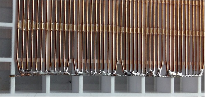
Once all of the rods have been soldered, use a pair of small wire cutters to snip out the wire between segments. This is another reason to use wire here - it cuts much more easily than the rod. When you are done, you should have all of the rods of each segment electrically connected to each other.
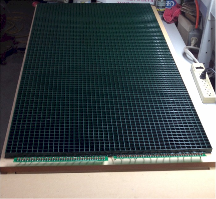
We will now do the same thing at the end of the louver - the other end of the rods. Pay very close attention that you have selected the same rod segments as in the center! In this case, you can lay the wire across the backs of the rods instead of on the ends. You can trim the excess rod length using a pair of heavy duty wire cutters. I placed a piece of wood under the rods when soldering on the back side to protect the surface of my work table.
Finally, attach a short length of wire to each of the segments at the end of the louver. Attach two wires to the center segment. These will be connected to the resistor network at a later time. The paper pieces on the wood are the layout for the board in work for the resistor network.
More TIG Rods
The next step is to glue the rods to the other end of the louver. First we need to cut the rods to length. We need about 11" of rod to cover the remaining open area of louver, plus some to hang over the edge. Since the rods are 36" long, cutting them into three 12" sections makes sense. These can be cut one at a time with heavy wire cutters, or a bundle can be cut at once. To cut a bundle, use hose clamps on each side of the bundle where you want to make the cut, then use a saw to cut through the entire bundle. If the clamp is close enough to the cut, it will prevent the rods from bending from the saw action. If they do get slightly bent, use that portion of the rod to hang over the edge - it will be trimmed off later anyway.
These rods are installed onto the louver just as above, using the all-thread for spacing and the E6000 to glue them down. When aligning the rods, make sure to abut them to the segment solder joints from before, and keep the same number of rods on each segment.
Continue in this same manner until the rest of the louver has rods affixed. Just as before, slightly bend the ends of border rods for each segment inwards and solder them to the copper wire. This will join the short portion of the segments to the long portion to make one continuous segment.
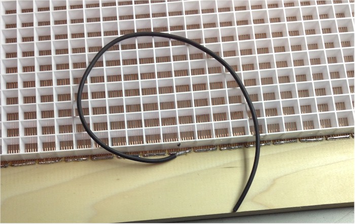
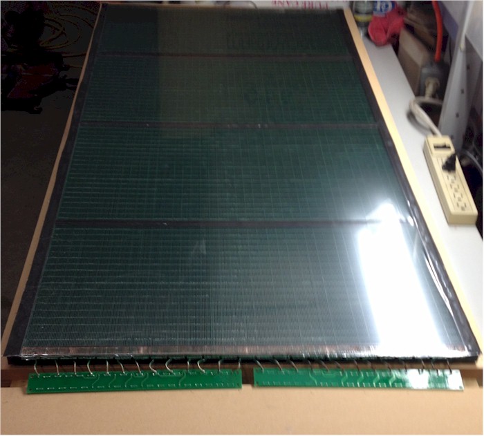
And, also like before, trim the ends hanging over the louver, then solder copper wire across the backs to join the segments at the other end. Unlike before, however, we will not be attaching short wires to each segment. This time we will attach a long flexible wire to the center segment only. This is the feed wire to the stator panel as a whole. I like to use test probe wire for these attachments. It is rated at 10kV, has silicone rubber insulation and is VERY flexible. I get it at my local electronics store (Torrance Electronics).
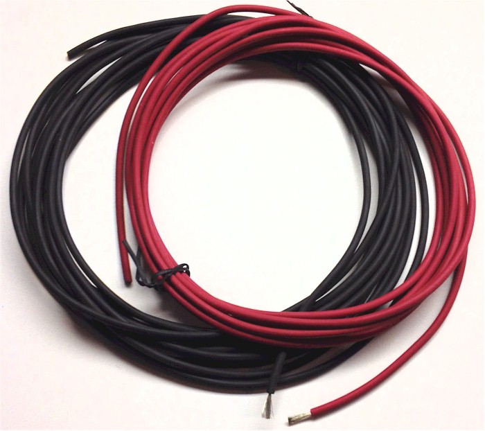
It is also available at Mouser in 50ft spools of Red and Black.
I have been using the black lead wire for the stator panel connection and the red wire for the HV Diaphragm bias connection but that is purely arbitrary. Solder a length of the lead wire to the center segment. I will be installing the electronics (HV supply, transformers, etc) into the bottom portion of the panel assembly, so this wire does not have to be long for me, in this case about 15".
Spacers
The next step is to add the spacers that will separate the stators from the diaphragm. For this build I have settled on 1/8" diaphragm to stator spacing (d/s). This is to allow the greater excursion necesary for reproducing lower frequencies. This is at the expense of efficiency!. If you are building a panel meany for 200Hz and up, for instance, then 1/16" d/s is a better choice. To aid in spacing, I will be using acrylic strips. These strips are 1/8" thick and 5/8" wide, 6ft long. I purchased them from ePlastics for just under $3 each.
One strip will be glued to the space at each side of the louver. Cut a 47" length from each of 2 strips for this purpose (keep the remainder for later). Inspect the side of the louver for any adhesive that may have oozed into the space for the strip and remove it using a kraft knife or razor blade. Be sure the area for the strip is clean and free of any dirt, debris, etc. this is important as we want our spacing to be consistent.
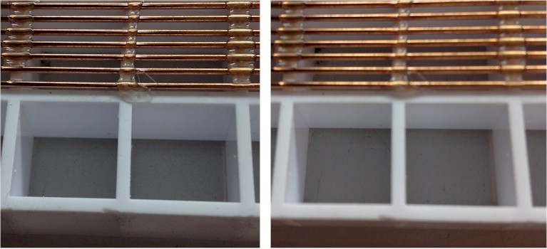
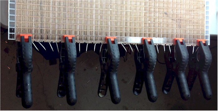
Apply a thin bead of adhesive along the two side rails, then affix the strip. Use clamps to be sure the strip is seated firmly against the louver. I use small spring clamps from Harbor Freight for this job.
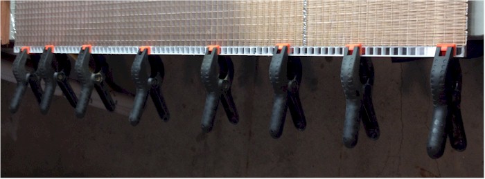
Next, we will affix a spacing strip along the top and bottom of the panel, directly on the rods. This is the reason that we did not place any adhesive on the last two vanes on each end. Cut the remaining strips to length to fit between the spacing strips that are on the side. Apply a bead of adhesive aling the two vanes on the end, then affix and clamp the spacer to the rods. The adhesive will seep between the rods and adhere to the vanes as well as to the strip. Be sure to use sufficient glue to allow this.
You will notice that the two spacers are not the same height. We will make them the same height in the end by applying tape to the spacers in a different manner when we prepare to make the diaphragm. The diagrams below show how the two spacers will end up the proper height in the end.
We will use double-sided scotch tape as an adhesive to hold the diaphragm on top of the spacer that rests on the rods, and we will use two layers of the double sided scotch tape plus 1/32" thick foam tape to affix the diaphragm on the side that rests directly on the louver. The extra layer of tape makes up for the difference in heights between the rods and the foam tape.
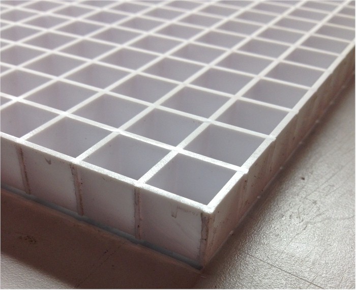
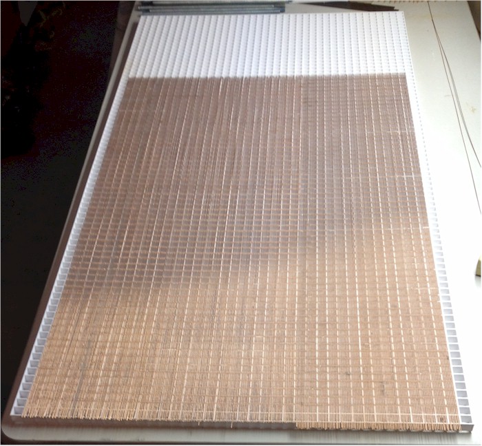
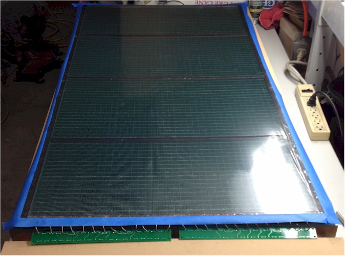
At this point, we should have a completely assembled stator panel:
Now, go back and repeat all of these steps 3 more times until you have a total of 4 stator panels just like this one. :)
Painting
The next step is to paint the stator louver panels. We do this so that the exposed wiring is electrically insulated. We are dealing with high voltages here, so we need to make sure everything is sufficiently covered. The first step is primer. The primer I use is, unfortunately, only available in a spray can. It is the Rustoleum Professional Primer, dull red color, just over $5 per can at Home Depot.
I use this primer instead of the standard gray primer as gray paint (as well as white) uses titanium dioxide as a coloring agent. This is a slightly conductive material. The red primer uses red talc as a coloring agent, which is insulative. To prep the louvers, remove with a craft knife any blobs of adhesive that have dripped onto the back of the louver. These will not cause any problems, but will be unsightly in the finished product. The next step is to mask off the surfaces of the spacers. This is not strictly required, but I have found that the tape used to hole the diaphragms adheres better to a clean acrylic surface than to a painted acrylic surface. I just used narrow painters tape for this.
Next spray paint the louver assembly using the primer. When spraying the back (non tig rod side), be sure to angle the spray can to hit the bottom corner of the louver cell. you will have to spray from 4 sades to get full coverage in the cell. When painting the front, be sure to spray from each side of the rod to get complete coverage. Be sure to let the paint dry between each direction so you avoid drips. This takes a lot of spraying, and uses up about 1 can of paint for each louver. When you have primed both sides, it should look like this:
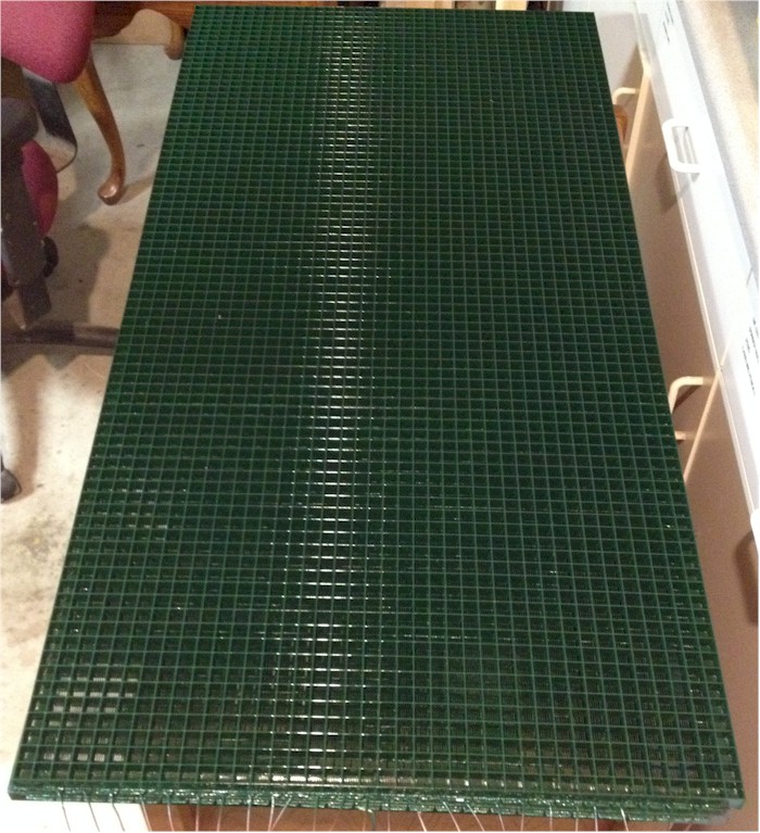
Next is to spray the color coat. In my case, I'm using Rustoleum Professional Enamel and a small spray gun. I chose a hunter green as I think it will look sharp with some cherry wood in my mostly green listening room. You can obviously choose any color you want - black is a very popular color choice.
I have to thin paint about 4 parts paint, 1 part Mineral Spirits to use the sprayer effectively. Again, be sure to spray from multiple directions to get a good coat on all sides. Many light coats is the key. The paint insulation is about 500V per mil of paint thickness. If we are looking at a few thousand volts potentially, then we will need several mils of thickness. In my case, I will be spraying a top coat of clear insulating varnish which is rated at 2500V/mil, so the paint only has to be thick enough to give a good coloring. When complete, it will look like this:
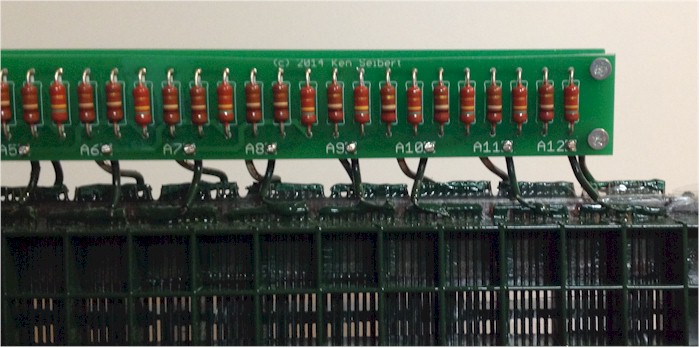
Resistors
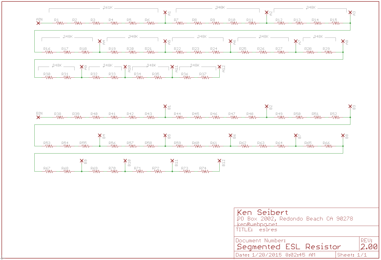
As noted before, each segment has to be connected to each other through a resistor network. The values for these resistors can be found using the spreadsheet referenced above. We are dealing with potentially high voltages in this setup, so some care has to be taken on resistor selection. Most resistors are rated for a few hundred volts at the most. If you are using a 100W amplifier, the output can be up to 50V. This then goes through the step up transformer with a ratio of 80:1 or more, meaning you can see a few thousand volts on the stators. The center segment see the most voltage, then as the signal goes through the rest of the resistor network, less and less voltage. For that reason, we need to allow for higher voltage capability on the center segments and less on the outer ones.
If a resistor is to see it's max rating of 500V, we can use Ohm's law to calculate the power dissipation required in the resistor: P = V2/R. In my case, we can use V=500V and R=348K. Plugging these values in gets just under 1W. To be safe, I am using 2W resistors. To keep under the 500V limit, I am assuming that the highest frequencies will not be continuous full power (unless I am running a sustained frequency sweep test), so by placing 6 resistors in series this gives enough protection against prolonged high frequency, high power signals. Since the next segment sees more signal content, but is already divided through the first resistors, 5 resistors in series would suffice here. progressively fewer resistors can be used in successive positions. I use Vishay 2W 5% 500V metal film resistors from Mouser. You could use others, but be sure to pay attention to voltage and power ratings.
Below is a diagram showing how these are to be wired up. The A side and B side are for the left and right sides of the louver panel since the segments are symmetric. you can click on the schematic to see a larger version.
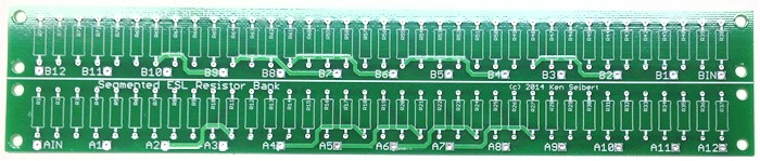
I like the reliability of using a PC board vs a hand wired board, so this was laid out as follows:
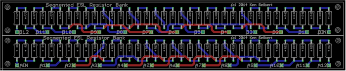
One of these boards is split into two (A side and B side) and one pair is used on each louver panel. This means that 4 boards (split into 8 halves) are required for the stereo pair of speakers. Here is the bare board as at came back from fab:
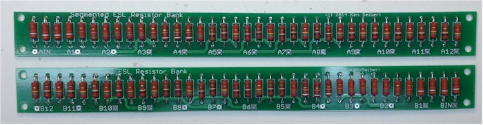
And after splitting the halves and soldering on the resistors:
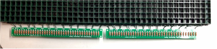
Now we solder the many leads from the louver panels to the appropriate points on the resistor boards. The A and B boards are for the left and right sides of the louver panel. The two wires from the center segment connect to the "A in" and "B in" pads, then each of the other leads down the line. Note that this is done before the final coatd of clear insulating varnish are applied. When we spray the clear coats, we want to spray the boards as well.
Clear Coat
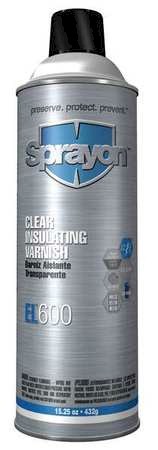
Now with the resistor boards attached, we will spray the entire assembly with the clear varnish. I am using the Sprayon Clear Insulating Varnish. It is about $5 for a good sized can. One can will do a couple of good coats on a louver panel. I get them from Zoro Tools
Again, just as with the paint, it is important to get an even coat on all sides of the TIG rod. This means spraying from multiple directions. Many light coats are preferable to one heavy coat. A heavy coat will tend to flow with gravity and be thick on the bottom and thin on the top. Light coats tend to stay in place by surface tension and will build upon each other.
After the clear coats dry, we can remove the painter's tape from the spacers. Be sure to allow plenty of time for the clear to dry completely before proceeding. Once we go to the next steps there will be no opportunity to do any touch up. The final product looks like this:
Diaphragm
Now we are ready to affix the diapgragm to the louver panels. First we will prepare one of the panels with the adhesive to to affix the diaphragm. Using the 3/4" wide double sided tape (not the foam tape), place 1 layer of tape on the top and bottom spacers, then two layers on the side spacers. Refer to the diagram we showed above...
Mid March 2015 Edit:
I had been listening to the speaker partially assembled while completing the rest of the wood working. After a couple of weeks, the scotch double sided tape (not the foam tape) failed, allowing the diaphragm to lose all tension. I separated the panels back apart (not easy with the foam tape) then repeated the process, but using 3M VHB (very high bondstrength) adhesive instead of the scotch tape. This seemed to do the trick.
Next we will apply one layer of 1/32" thick foam tape to the side spacers. This will make the side and top spacers the same thickness.
Now we will place the internal spacers. The largest unsupported width for the diaphragm should be no more than 100 times the diaphragm to stator spacing (d/s). In this case, the d/s is 0.125" meaning that the largest spacing should be no more than 12.5". We have a solder joint toward one end and would prefer to have one of the spacers cover that joint. We will have two more spacers divided equally among the rest of the stator panel. For the spacer over the solder joint, we will use a 3/4" wide spacer. Since the solder joint bulges upward slightly, we will use a slightly thinner spacer on this one than on the other two. To make the thickness, we will use foam tape. In this case either 3 layers of the 1/32" thick tape, or since I have some 1/16" thick foam tape, I'll use one layer of that and one of the 1/32".
For the other two spacers, I'll use a craft knife to split the tape into 3/8" widths, then use 2 layers of the 1/16" thick tape to make the 1/8" thick spacers.
The material I used for the diaphragm is a 6 micron mylar purchased from a vendor on ebay. It is $30, free shipping and 40m long, enough to do many panels with extra for goofs or experimentation.
Electrostatic Speaker Membrane Dupont Mylar C 6um 40M
The mylar has to be under tension. If you do not tension it, then the diaphragm will flop around until it sticks to one stator or the other. After that, no sound. When you tension the diaphragm, it acts as a drum head, vibrating with a resonant frequency. The higher the tension, the higher the frequency. The balancing act is to tension the diaphragm enough so that it behaves reliably but not so tight as the resonance is too high.
There are two means of tensioning the mylar to make the diaphragm. One method is to stretch the material, and the rule of thumb is that it the mylar should be stretched 1% to 1.5% to achieve the proper tension. Another method is to use heat to shrink the mylar. In our case, I plan to stretch the mylar using a stretching jig, then to later tune the resonances using heat.
The photos below show how I constructed a stretching table. The idea was to have a small moveable piece at the end which could be drawn out by turning some bolts. 1/4" marks on one of the legs tells me how far the mylar has been stretched. I taped the mylar at the top and bottom very well, then turned the bolts to the proper stretching level, then manually pulled and taped the sides to remove any wrinkles in the mylar. In this case, I had a piece of mylar that was 52" long. Stretching 1.5% of this length worked out to about 3/4".
Here is the mylar on the stretching table, under tension, ready for the stator panel.
Then with all the paper backing removed from the louver panel to expose the adhesive, Lay the panel carefully on top of the prepared mylar and press down to firmly affix the diaphragm.
Then use a craft knife to trim the excess mylar from the louver panel.
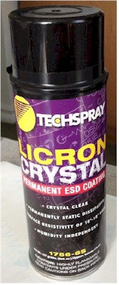
The next step is to coat the Mylar. Mylar, in and of itself, is non-conductive, so in order to retain the charge on the diaphragm, the entire diaphragm should have an electrical resistance of 10^9 to 10^12 Ohms. Entire schools of thought and process have come about regarding coatings. A perusal of the Exotics section of http://www.diyaudio.com will give you a dozen coating formulas or processes. Everything from dish soap to craft glue to graphite and cotton balls. I have had excellent results using an anti-static spray product called Licron Crystal. It sprays on easily, dries quickly, and is impervious to humidity. One thin complete coat is all you need. It gives a surface resistance on the low end of the desired range, but works really well. I purchased it through Mouser. The other coatings have their main attractiveness in that they are very inexpensive. Licron is not. It is about $40 per can, which contains enough to do several panels. I am still on my first can of Licron and have made well over a dozen panels of various sizes before settling on this design.
You don't need or want to coat the diaphragm all the way to the edge of the Mylar, only about halfway through the edge tape, so you can use painters tape to mask off the places you don't need to coat. Lay the panel with the diaphragm flat, with the diaphragm up. Spray a thin coat of Licron over the surface of the diaphragm, using enough spray to just wet the entire surface. The spray is mostly solvent, which will evaporate leaving a very thin, clear coating of slightly conductive material.
Do your best to do the coating in as clean and dust-free environment as possible. Everything will stick to the Licron when it is wet. Be sure to dust off the Mylar before coating. This panel was just sprayed with Licron and you can see a slight haze to the Mylar where the coating is still just wet.
The instructions on the can say to allow 24 hours for complete curing – believe it. The foam tape will not adhere easily to uncured Licron. I have found it best to allow even more time for curing before proceding, especially if I am doing a panel in the winter (well, OK, Southern California winter) where the temperature is below room temperature and humidity is high. In the hot, dry summers here, the curing is far faster.
Now we need to prepare the second louver panel just as the first with the tape and spacers. Be sure to line up the spacers so that they are in the same place on both louver panels.
Once the diaphragm is tensioned and coated, a method has to be in place to allow charge to be placed on the diaphragm. In this instance, it is two strips of copper on the sides of the diaphragm, hidden between the layers of tape. I chose an adhesive-backed copper strip as the material for the strips. It is available from a number of sources, but as I was ordering the foam tape from Uline , that seemed as good a place as any to purchase the copper tape.
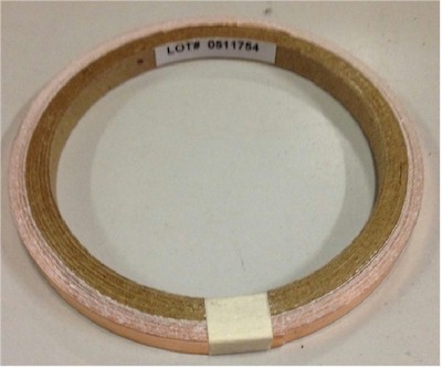
Copper Tape at Uline It is about $23 for 18 yards. Alternatively, McMaster-Carr has it for about $7 for a 6 yard roll (part number 76555A721) Copper Tape at McMaster. For the size stators we are making, you will need about 8 feet, or 16ft for a stereo pair. Depending on just how careful you are, you may make it with one of the 6 yd rolls.
On the second louver panel affixed with the double sided tape, I remove the backing, then lay down a strip of the copper tape in the center of the strips.
A connection must be made to the charge strips to the high voltage supply, so this must be soldered onto the copper tape before sticking it onto the panel. The copper solders easily, but the real trick is to make sure the solder joint is as thin as possible. Use fine stranded wire for this and fan out the strands of the wire so that they all lay flat on the copper. Let the solder flow onto the copper keeping it very thin – do not allow it to ball up. Use some fine sandpaper after the joint cools to knock off any rough spots, remember, sharp edges and points are too attractive to corona arcing and can ruin a completed panel. By sealing the charge strip well inside the tape strip, the chance of arcing is greatly reduced.
Now you have the two halves of the stator assembly. Align one to the other so that the tape holds them together and press to make a good seal.

The last step is to affix the resistor boards to each other using nylon spacers and screws. With the boards attached to each other and to the louvers with many wires, it makes a very sturdy assembly.
This completes the stator assembly process! Now repeat all of these steps to create a second stator for the other stereo channel.

Parts List
| Item | My Source | Price | Qty 1 Panel | Qty 4 Panels |
| Louver Panel, 1/2" thick, Acrylic | Central Lighting Plastics. | $25 | 1 | 4 |
| TIG Rod, ER70S-02, 36" long, 0.035" dia, 10 lb | Gardena Welding Supply | $65 | 2 | |
| Acrylic Strips, 0.125"x0.625", 6ft long | ePlastics | $3 | 2 | 8 |
| HV Probe wire, Black | Mouser | $25 | - | 1 |
| E6000 Adhesive | Amazon | $3 | 3 | 12 |
| Double-sided Foam Tape, 3/4" wide x 1/32" thick | Uline | $17 | 1 | |
| Scotch Double-sided Permanaent Tape, 3/4" | Staples | $11 | 1 | |
| 1/2"-13 All-thread, 1ft length | Home Depot | $2 | 4-6 | |
| Rustoleum Red Professional Primer | Home Depot | $5 | 1 | 4-5 |
| 20ga Copper wire | box in garage | - | 6ft | 24ft |
| Resistor Board | KenSeibert.Com | - | 1 | 4 |
| Resistors | Mouser | $0.16 | 74 | 296 |
| Clear Insulating Varnish | Zoro Tools | $5 | 1 | 4 |
| Licron Ctystal Spray | Mouser | $40 | 1 | 1 |
| Copper Tape | McMaster | $7 | 1 | 1 |