 |
Projects
|
Projects Welcome To KenSeibert.Com Audio
To help you assemble the items required for constructing the Electrical Panel, there is a parts list at the bottom containing the items, sources and pricing.
The Electrical Panel
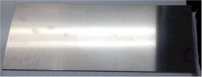
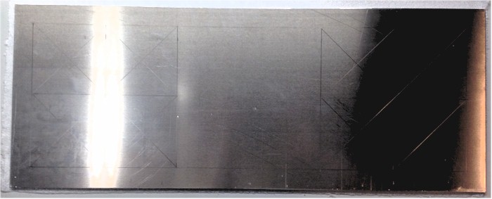
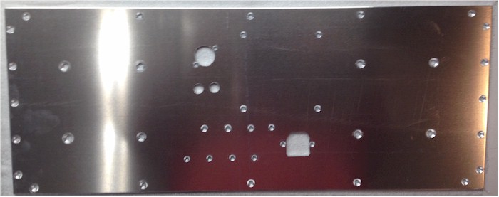
We start with a blank piece of aluminum sheet. I like to use 6061-T6 as an allow of aluminum as it is hard and strudy enough to resist bending, yet soft enough to work easily. Cut 2 Size Metals does a good job with fast turnaround for very reasonable prices. A 23"x9" piece, 0.125" thick cost about $21. The prices will vary based on raw aluminum prices.
I chose this size as in the final assembly, my speaker will be 23" wide. The panels are 22 1/2" wide, and allowing for 1/8" walls on each side channel frame and 1/8" each side cushioning material, we have a total width of 23". I am allowing 1" around the perimeter for mounting to the speaker frame, which gives me an area of 21"x7" to mount the components.
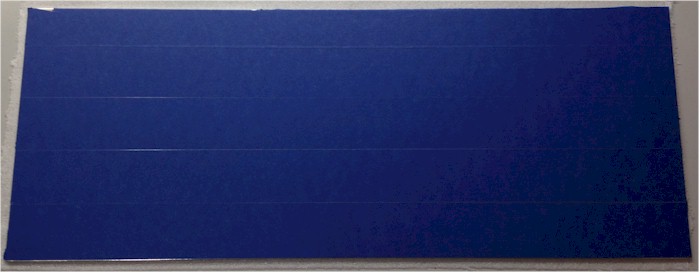
The very first thing I usually do when I get the metal is to find the best looking side. Usually, one side has more scratches, dings, etc than the other side. We want the "good" side to be the one that the public will see, so we want to keep it looking good. The other side is the one on the inside of the speaker, we don't really care about that side. Sometimes metal will come with a protective coating on one side. If that is the case, leave it there - that is the good side. In this case, there is not a protective film, so I'll add a covering of painter's tape to protect that side from damage while I am working on the panel.
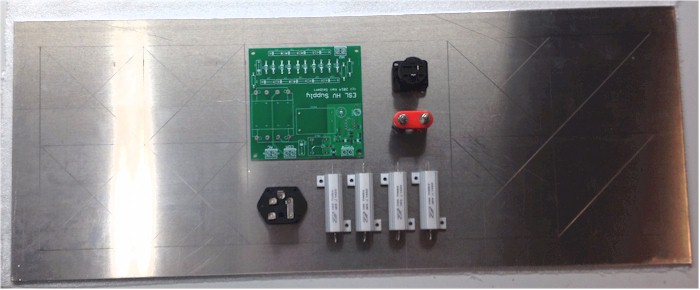
I will need to mount the following to the panel:
- A High Voltage Supply board
- A 120V power receptacle w/ fuseholder
- Binding Posts and a Speak-on Jack for speaker inputs
- Up to Four Power Resistors
- Up to 8 Toroidial Transformers.
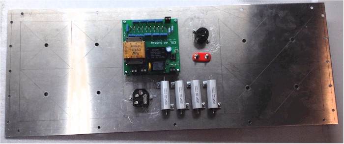
Placing these items on the panel to give a rough layout I get this:
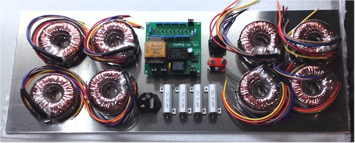
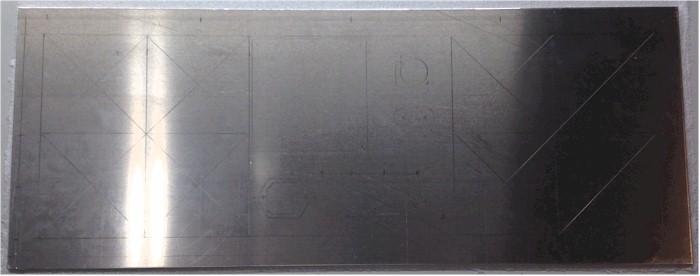
To allow for proper drilling and metalwork, mark the positions of all of the components. First, we will mark out the mounting area along the edges. A 1" band where we will place no components. This will provide an area for the panel to attach to the frame of the speaker.
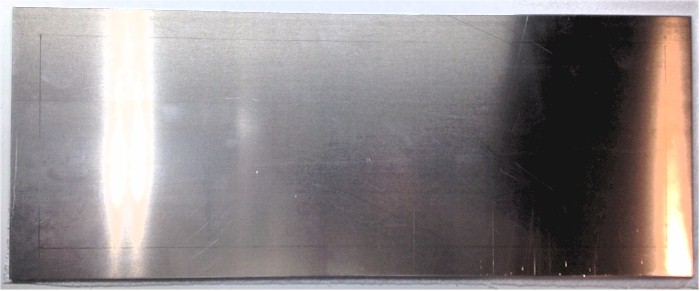
Each of the transformers is just over 3" in diameter. If we allow a space of 3 1/2" this will give some room to work. We have a 7" work area, so divide that in half and mark off 4 of the 3.5" squares on each side. Draw lines diagonally through each square to find the center. The center of each square is where the mounting hole will be drilled.
Place the board, speaker connectors, AC receptacle and resistors on the panel in the remaining area.
Trace around each component and mark the hole locations and any areas that have to be removed for the parts to fit.
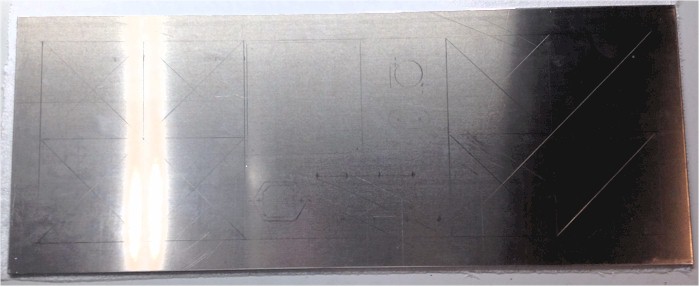
Finally, mark the locatio0ns of the panel mounting holes. These will be 1/4" in from each side (the frame channel is 1/2" thick), and 3/8" from the top and bottom edges (the wood strips are 3/4" thick). Allow for several screw locations along each edge.
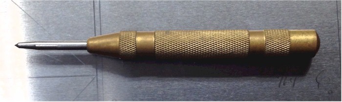
Now we are ready to drill the holes for mounting the components to the panel. All of the holes we drill will be counter-sunk to make for a more attractive look. So, we want to drill from the back of the panel (the side we marked up) and have the drill exit the front of the panel. Any burring will be taken care of by the countersink process. It is advantageous to center punch the hole locations. This will help the drill to stay aligned when making the holes. I use a centerpuch tool that is spring-loaded and snaps a divot into the metal where I want the hole. Other center punches are manual and require a hammer. i don;t remember where I got this one, I have had it for many years. Harbor Freight has one for about $3.
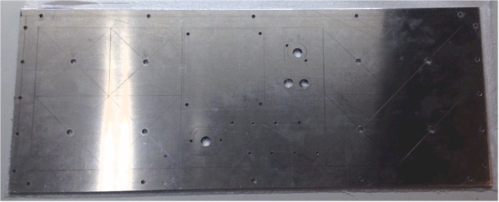
I am using #8 screws to attach the panel to the speaker, so these are drilled along the edges. Consult a table such as this one to find the right clearance drill size for each machine screw type. The HV Supply board attaches with #6 screws, the speak-on, power resistors and power entry module with #4 screws. I am not using the #10 screws that came with the transformers as they are not flat-head style, so I am using some 1/4-20 flat-heads instead. The Binding posts require a 15/32" hole and I am using the same drill for pilot holes for the body of the power entry module and the speak-on connector. When these have been drilled, it will look like this:
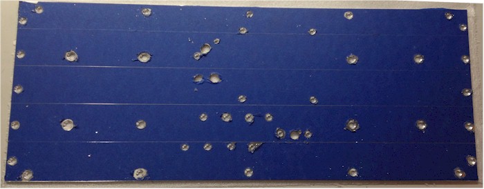
Flipping the panel over, I use a countersink bit in the drill press to countersink the holes that will require it. Have a sample of each type of screw on-hand so you can check for the proper depth of countersink.
I am not a very proficient metalworker, so I go with the skills I have. I used a hand jig saw and a file to make the larger openings for the Speak-On connector and the power receptacle.
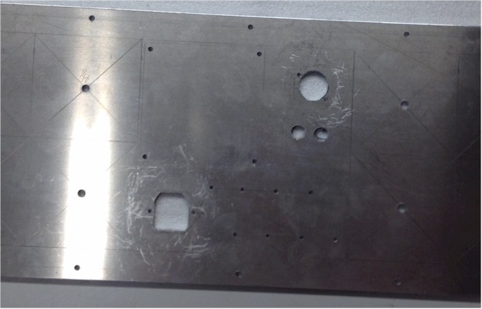
This completes the metalworking, so now remove the protective tape from the front of the panel.
Now mount the components to the panel. I am mounting everything except the transformers first. When I wire these up, I don't have to deal with the weight of the transformers. I'll do those last.
First wire up the AC mains. The green wire is the safety ground and should be connected to the chassis. In this case, it is connected via a ring lug to the mounting screw for the AC line receptacle. This is an important safety measure! Next wire the HOT leg of the AC. This is the black wire which comes from the fuse portion of the AC receptacle. The circuit board has the AC contacts labelled as H or N for HOT and Neutral. Lastly wire the neutral line (white) to the N pin of the AC.
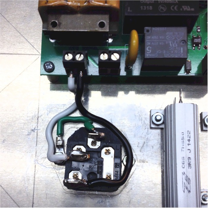
The speaket inout lines are wired next. The Speakon connector has the pins labelled as +1 and -1. Wire the +1 to the RED binding post and the -! to the BLACK post. In the photo below you will notice that the -1 wire has no insulation. This is so we can solder more wires to this portion later. Thread a wire through all the resistors at each end and solder into place. Wire from the Red post to the top of the resistors, then from the top of the resistors to the Audio In + on the circuit board. Wire fromt he black binding post ot the Audio In 1 on the circuit board. This completes the speaker wiring.
Mount the transformers to the board. You must use an even number of transformers. The power from the amplifier is divided among the transformers. If you are using this ESL as a midrange/high speaker and crossing it over above 200Hz, them most of audio power is concentrated in the bass, and this speaker will not see it. These transformers are rated at 50VA at 50Hz. Two transformers sharing the load means about 100vA power handling at 50Hz. If these are crossed over at 200 Hz, then they can handle 4 times the power (200/50) or about 400VA.
On the other hand, since we are working on a full range speaker, we need to go the other way. At 25Hz (half the frequency), the transformers can only handle 25VA (half the power) each. Allowing for a 100W amp would require 4 transformers, so to be safe, initially I am using 6, with the place in the panel to add two more.
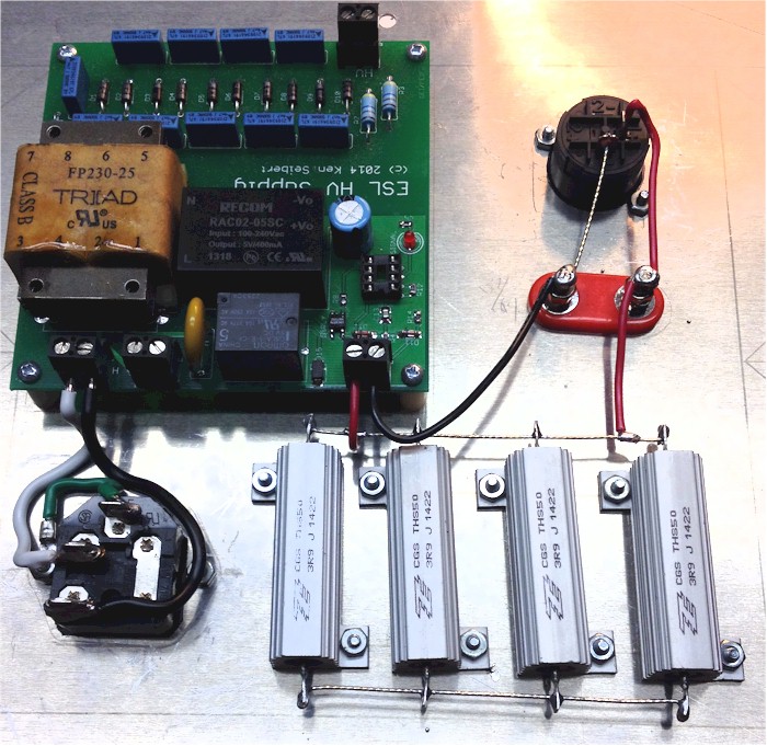
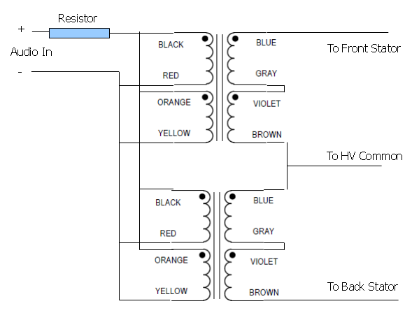
Each transformer is wired as above. In this case, the secondary of the transformer is our primary - we are using the transformer as a step-up, not a step down. We will wire the low-voltage windings in parallel and the high voltage windings in series. If you are using just 2 transformers, the wiring would look like this:
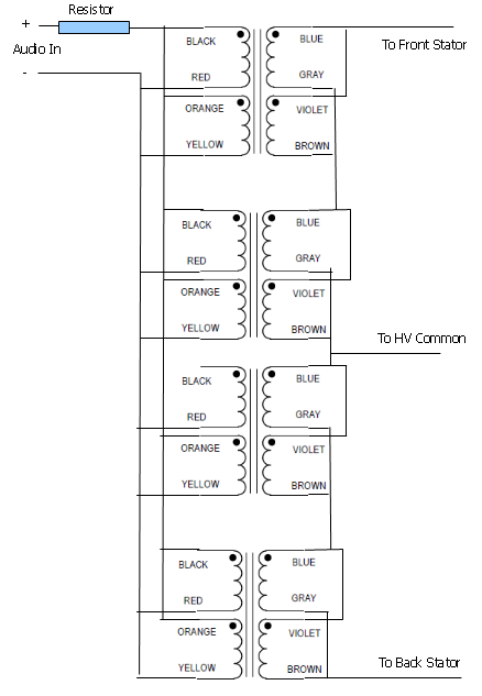
We will just expand on this theme for wiring the 6 transformers. When wired it looks like this:
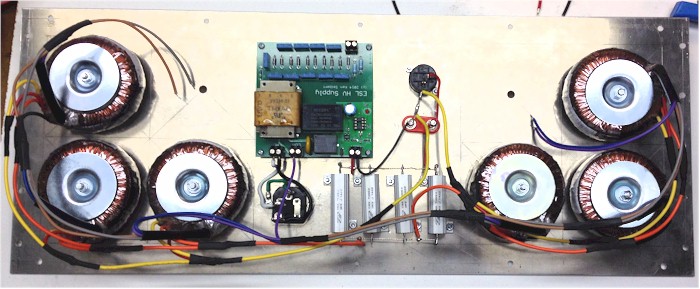
I used some wire ties to dress up the appearance and now it is complete. The pair of wires to the left go to the rear stator, the pair to the right to the front stator.
Parts List
| Item | My Source | Price | Qty per Speaker | Qty per Pair |
| 0.125" Aluminum Panel 6061-T6, 23"x9" | Cut 2 Size Metals | $21 | 1 | 2 |
| Triad Power Transformer | Mouser | $37 | 2 (up to 8) | 4 (up to 16) |
| Power Entry Module w/ Fuse | Torrance Electronics | $2 | 1 | 2 |
| Speak-on Jack | Mouser | $3 | 1 | 2 |
| Power Resistors, 4 Ohm, 50W | Mouser | $3 | 4 | 8 |
| High Voltage Power Supply Board | KenSeibert.Com | $40 | 1 | 8 |